Gradient adjusting type self-cleaning infrared monitor

A technology of self-cleaning and monitoring, applied in cleaning methods and utensils, cleaning methods using tools, chemical instruments and methods, etc., can solve the problems of easy dust falling, inability to filter infrared rays, etc., and achieve cleanliness, good adaptation effect, The effect of good imaging effect

Active Publication Date:
View PDF9 Cites 6 Cited by
  • Summary
  • Abstract
  • Description
  • Claims
  • Application Information

AI Technical Summary

Problems solved by technology

[0006] The purpose of the present invention is to provide a gradual adjustment self-cleaning infrared monitor that uses temperature control to solve the problem that the existing infrared monitor cannot be filtered according to the intensity of infrared rays and is easy to fall into dust.

Method used


Image

  • Gradient adjusting type self-cleaning infrared monitor
  • Gradient adjusting type self-cleaning infrared monitor
  • Gradient adjusting type self-cleaning infrared monitor

Examples


Embodiment 1

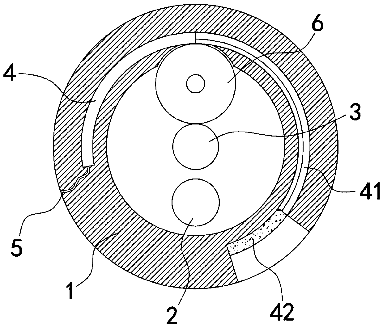
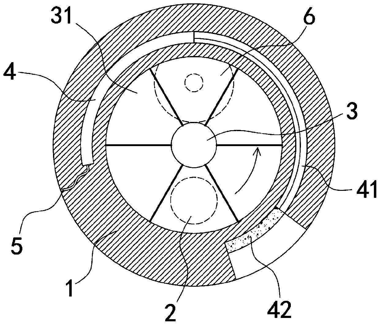
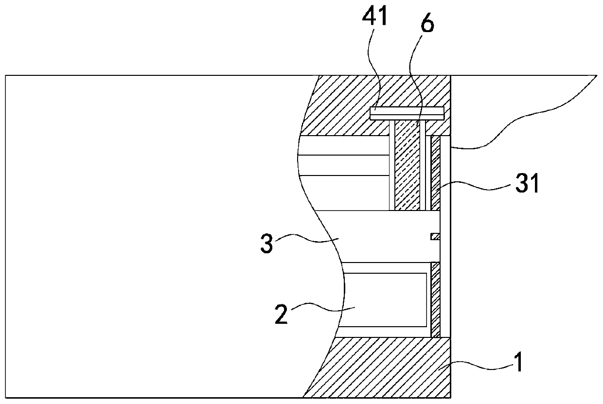
[0021] Such as Figure 1-3 As shown, a gradually adjustable self-cleaning infrared monitor includes a cylindrical housing 1 and a monitoring head 2, the monitoring head 2 is installed on the lower half of the housing 1, that is, the monitoring head 2 is installed on the axis of the housing 1 At the following positions, the center of the housing 1 is coaxially connected to the drum 3, and the front side wall of the drum 3 is fixedly connected to the filter plate 31, and the filter plate 31 is spliced ​​by a plurality of fan-shaped plates with successively increasing filter intensity. , and the filter intensity of multiple fan-shaped plates for infrared rays is along the figure 2 The directions of the arrows increase in turn. Specifically, the infrared film can be pasted on the fan-shaped boards to achieve infrared filtering, and different layers of infrared films can be pasted on each fan-shaped board to achieve different filtering intensities. In the initial state, the same a...

Embodiment 2

[0026] Such as Figure 4 As shown, the difference between this embodiment and Embodiment 1 is that: the outer front end of the housing 1 is rotatably connected with a circular transparent plate 7, and the transparent plate 7 is provided with an arc-shaped tube 8 concentric with the transparent plate 7, One end of the arc tube 8 is airtightly connected to the pressure stabilizing passage 5, and the other end is open. A magnetic piston block 81 is connected to the arc tube 8 in a sealed and sliding manner. The connecting strip 71 sucked, the piston block 81 can drive the connecting strip 71 to move thereupon when sliding along the arc tube 8, the front end side wall of the housing 1 is fixedly connected with the cleaning strip 72 that fits the transparent plate 7 and arranges.

[0027] In this embodiment, when the arc-shaped friction strip 41 rotates, the air in the arc-shaped cavity 4 will be squeezed into the arc-shaped tube 8 through the pressure-stabilizing passage 5, and th...


PUM


Abstract

The invention belongs to the technical field of monitoring equipment, in particular to a gradient adjusting type self-cleaning infrared monitor. The monitor comprises a cylindrical shell and a monitoring head, the monitoring head is arranged at the lower half part of the shell; a rotary drum is coaxially and rotationally connected to the center of the shell. The side wall of the front end of the drum is fixedly connected with a light filter plate; the light filtering plate is formed by splicing a plurality of fan-shaped plates of which the light filtering intensity is sequentially increased; an arc-shaped cavity is formed in the side wall of the shell; one end of the arc-shaped cavity is closed, the other end of the arc-shaped cavity is communicated with a pressure stabilizing channel, anarc-shaped friction strip is slidably and hermetically connected into the arc-shaped cavity, expansion liquid is filled between the arc-shaped friction strip and the closed end of the arc-shaped cavity, a friction wheel is rotatably connected into the shell, the lower end of the friction wheel contacts with the side wall of the drum, and the upper end extends into the arc-shaped friction strip. According to the invention, the light filter plate is formed by splicing the plurality of fan-shaped plates of which the filtering intensities are sequentially increased, and the light filter plate canbe adjusted according to different illumination intensities, so that a better imaging effect is achieved.

Description

technical field [0001] The invention belongs to the technical field of monitoring equipment, in particular to a gradually adjustable self-cleaning infrared monitor. Background technique [0002] With the increasing popularity of closed-circuit surveillance in civil and commercial purposes, surveillance cameras are widely used in various fields to protect enterprise management and social security. Monitors are widely used in residential buildings, real estate villas, shopping malls, and financial offices. [0003] Infrared monitors on the market are generally equipped with infrared filters, which are used to filter infrared rays under strong sunlight, reduce interference to imaging, and improve shooting clarity. In addition, during use, filter switches are generally used Switch the filter, use the infrared cut-off filter during the day to restore the color; at night, use the fully transparent filter to increase the amount of light entering and improve the night vision effect...

Claims


Application Information

Patent Timeline
Patent Type & Authority Applications(China)
IPC IPC(8): H04N7/18B08B1/02
CPCB08B1/02H04N7/18
Inventor 王金鑫饶杨扬闫慧强
Why Eureka
Try Eureka