Valve Inserts and Air Bleed Valves

An air discharge, insert technology, applied in the direction of control valves, valve devices, vehicle components, etc., can solve the problems of opening stroke maintenance, difficult to build size, etc., to achieve the effect of increasing emissions

Active Publication Date: 2022-03-22
WD RACING
View PDF8 Cites 0 Cited by
  • Summary
  • Abstract
  • Description
  • Claims
  • Application Information

AI Technical Summary

Problems solved by technology

[0007] The disadvantage of the discharge valve described above is that the valve insert has two conical surfaces, the lower surface of the valve disc and the abutment surface of the retaining member, which have high dimensional accuracy requirements in order to adjust the opening stroke of the valve stay within desired limits
Due to the difficulty of constructing dimensionally accurate tapered surfaces, valve opening strokes may exceed allowable limits

Method used


Image

  • Valve Inserts and Air Bleed Valves
  • Valve Inserts and Air Bleed Valves
  • Valve Inserts and Air Bleed Valves

Examples


Embodiment Construction

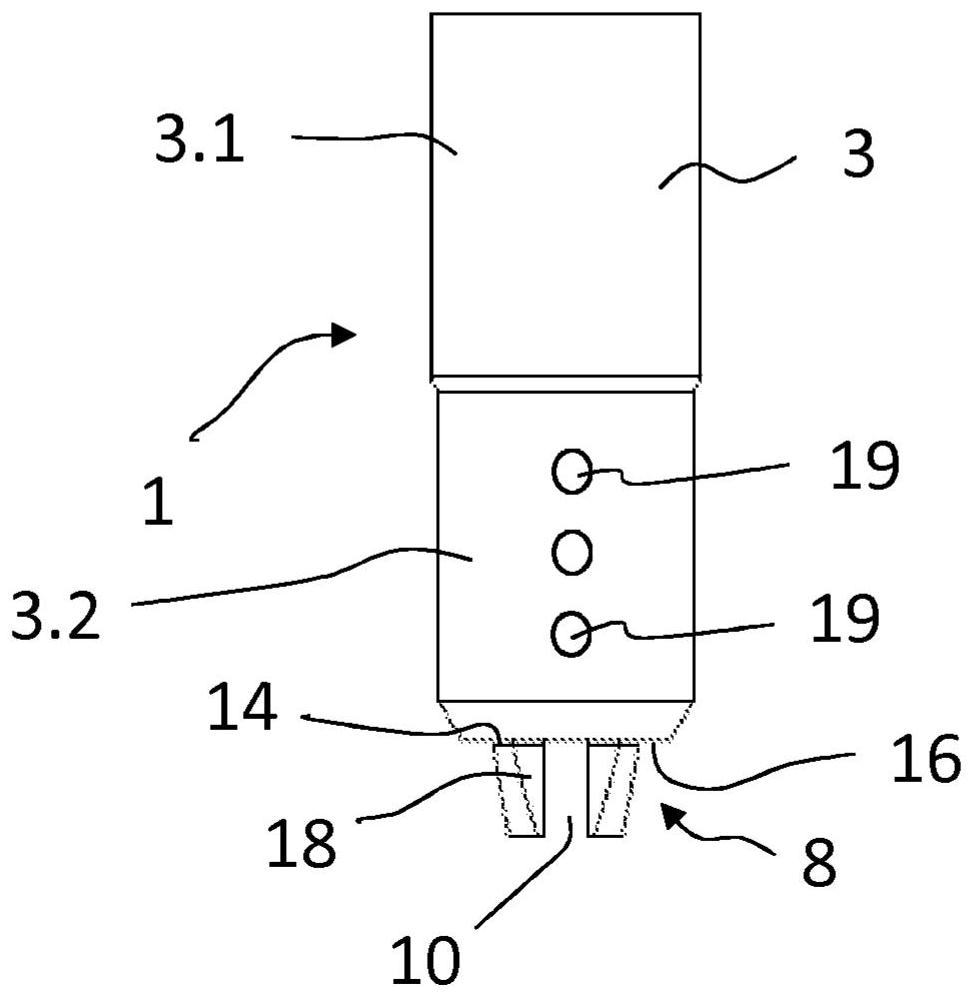
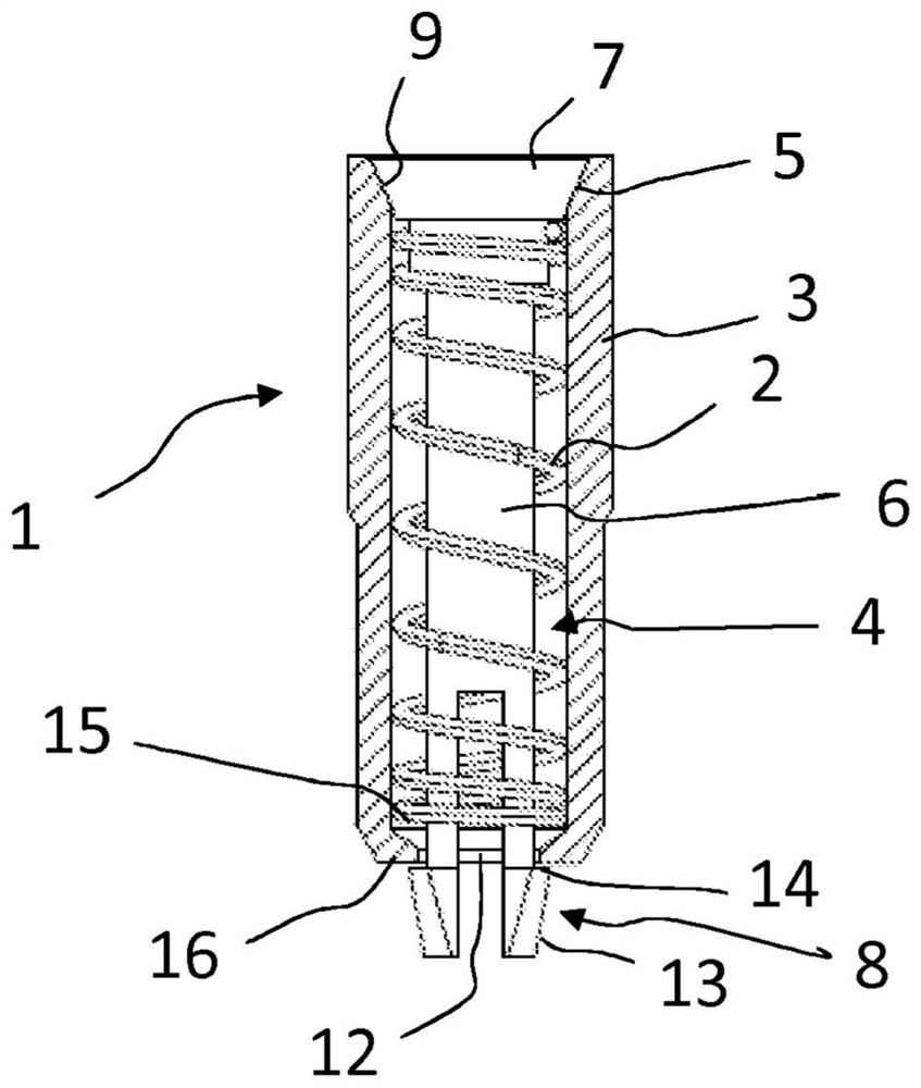
[0020] figure 1 and figure 2 Shown is a vent valve 1 for venting air from within a vulcanization mold, for example a vulcanization mold for vehicle tyres. Usually, a vulcanization mold includes 1000-4000 discharge valves 1 . The discharge valve 1 includes a valve sleeve 3 and a valve insert 4 inserted into the valve sleeve 3 . The valve sleeve 3 is attached to the discharge hole of the vulcanization mold by means such as press fit. The valve sleeve 3 is cylindrical. The outer diameter of the valve sleeve 3 is usually 1.5-4mm. exist figure 2 , the valve sleeve 3 is shown in cross section.

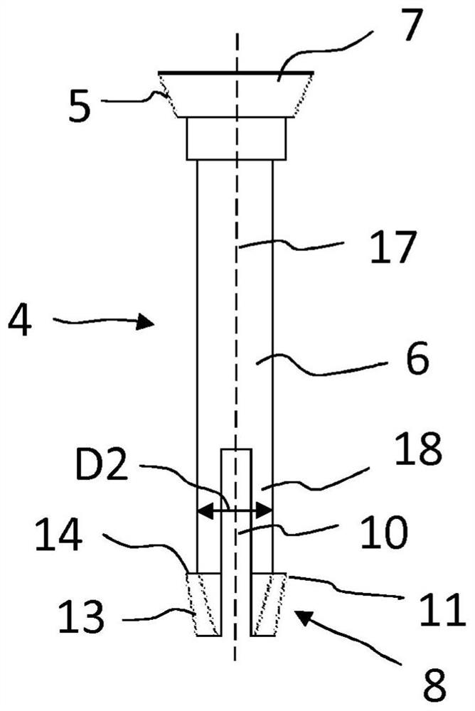
[0021] The valve insert 4 comprises a valve stem 6 provided at a first end with a valve disc 7 and at a second end of the valve stem 6 with a mechanism or means 8 for removing the valve insert 4 Attached to the valve sleeve 3. The valve insert 4 is attached to the valve sleeve 3 by a detachable connection. exist Figure 3-Figure 5 The valve insert 4 is shown in more detail in . ...


PUM


Abstract

A valve insert (4) for use in an air discharge valve (1) of a vehicle tire vulcanization mold, wherein the valve insert (4) comprises a valve stem (6) arranged In order to be inserted into the valve sleeve (3) of the air discharge valve (1), the first end of the valve stem (6) is provided with a valve disc (7), and the second end of the valve stem (6) is provided with an elastically compressible A retaining member (8) for removably attaching the valve insert (4) to the valve sleeve (3) and for limiting the opening stroke of the valve insert (4). The retaining member (8) comprises a stop surface (14) arranged to abut against the end face (16) of the valve sleeve (3), thereby limiting the opening stroke of the valve insert (4).

Description

technical field [0001] The present invention relates to a valve insert for an air discharge valve and an air discharge valve for discharging air from a curing mold, for example from a curing mold for a vehicle tire. Background technique [0002] In a vulcanization mold for vehicle tires, a green tire tire smaller than the internal dimensions of the mold is placed inside the mold, and then the mold is closed. After the mold is closed, the tire blank is inflated and in its plastic state is pressed against the mold surface to give the tire its size and shape. During the vulcanization process, in order to bring the surface of the tire green body into close contact with the mold surface, the air between the tire green body and the mold surface must be discharged. The curing mold includes vent holes through which air can be vented from the space between the green tire and the mold surface. Typically, curing molds include hundreds of vent holes to completely evacuate air at every...

Claims


Application Information

Patent Timeline
Patent Type & Authority Patents(China)
IPC IPC(8): B29D30/06B29C33/10F16K24/04
CPCB29C33/10B29D30/0606F16K24/04B29D2030/0617F16K15/063B29D30/0601B60C2019/008B60C19/00B29D30/0662
Inventor 佩卡·彭基米基
Owner WD RACING
Why Eureka
Try Eureka