
Insulation device for turbine casing, fixing device for insulation block and fixing method

一种涡轮壳体、保温装置的技术,应用在燃气轮机装置、喷气推进装置、机器/发动机等方向,能够解决作业工序增多等问题

Active Publication Date: 2022-04-08
MITSUBISHI POWER LTD
View PDF15 Cites 0 Cited by
  • Summary
  • Abstract
  • Description
  • Claims
  • Application Information

AI Technical Summary

Problems solved by technology

However, in Figure 4A In the fixing structure of the heat insulating block to the turbine casing shown in , since it is necessary to laminate multiple layers of heat insulating material 102 and heat insulating block 103, the number of work steps increases and a large number of installation man-hours are required.

Method used


Image

  • Insulation device for turbine casing, fixing device for insulation block and fixing method
  • Insulation device for turbine casing, fixing device for insulation block and fixing method
  • Insulation device for turbine casing, fixing device for insulation block and fixing method

Examples


Embodiment Construction

[0060] Hereinafter, embodiments of the present invention related to a heat insulating device for a turbine casing, a fixing tool for a heat insulating block for a turbine casing, and a fixing method for a heat insulating block for a turbine casing will be described with reference to the drawings.

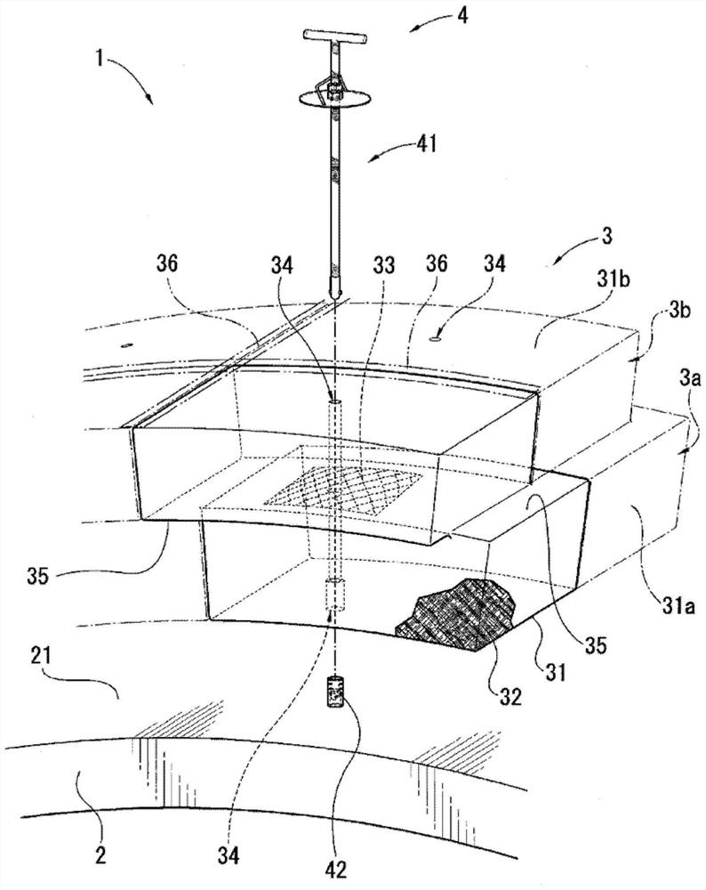
[0061] use figure 1 The heat-retaining device for a turbine casing according to this embodiment will be described. For example, if figure 1 As shown, the turbine casing heat insulating device 1 covers the surface 21 of the turbine casing main body 2 of a turbine generator used in a power plant or the like to keep the turbine casing main body 2 warm. The thermal insulation device 1 includes a thermal insulation block 3 and a fixing tool 4 for fixing the thermal insulation block 3 to the surface 21 of the turbine casing main body 2 .

[0062] The thermal insulation block 3 has: a first thermal insulation block 3a, which directly covers the surface 21 of the turbine casing main bod...


PUM


Abstract

The fixing device (4) of the heat insulating block (3) covering the turbine casing main body (2) has: a fixing rod (41) having an engaging part (431) including a protrusion (412) at one end; and a socket (42). The socket (42) has a guide groove (421) into which the protrusion (412) of the fixing rod (41) enters, and a recessed groove (422). The guide groove (421) has: a first guide groove (421a) extending from the start end (A1) to the end end (B1) along the axis direction of the socket; and a second guide groove (421b), the start end A2 is connected with the end end B1, along the axis relative to the The circumferential direction of the socket axis extends from the start end A2 to the end end B2. The second guide groove (421b) is connected with the recessed groove (422).

Description

technical field [0001] The invention relates to a thermal insulation device for a turbine casing, a fixing device for a thermal insulation block for a turbine casing, and a fixing method for a thermal insulation block for a turbine casing. [0002] This application claims priority based on Japanese Patent Application No. 2017-094451 for which it applied in Japan on May 11, 2017, and uses the content here. Background technique [0003] In general, the turbine housings of steam turbines and gas turbines (hereinafter collectively referred to as "turbine generators") used in power plants, chemical plants, etc. are divided into upper and lower parts with the center axis of the rotating part such as the rotor as the boundary. . The upper case and the lower case are fastened to each other by bolts at respective flange portions. Stationary parts such as vanes are provided on the inner surface of the turbine casing. Rotating parts such as a rotor to which buckets are attached are ...

Claims


Application Information

Patent Timeline
Patent Type & Authority Patents(China)
IPC IPC(8): F01D25/24F01D25/10F01D25/28F02C7/00F02C7/24F16B5/00
CPCF01D25/10F01D25/24F01D25/28F02C7/00F02C7/24F16B5/00F01D25/08F01D25/14F01D25/145F01D25/246F05D2220/31F05D2220/32F05D2260/231F05D2300/5024F05D2260/31F05D2220/30F05D2230/51F05D2230/60
Inventor 阿部飞太黑川祐二和泉卓也中尾猛井手启介古贺理
Owner MITSUBISHI POWER LTD
Learn More