Control System And Method For Controlling A Rectifier

a control system and rectifier technology, applied in the direction of power conversion systems, ac-ac conversion, dc conversion with intermediate conversion, etc., can solve the problems of increasing the manufacturing and maintenance cost of the rectifier control, increasing the amount of service and maintenance time, etc., to achieve simple and fast setting up of the rectifier, more robust, and the effect of setting the behavior

Active Publication Date: 2016-02-11
ABB (SCHWEIZ) AG
View PDF5 Cites 0 Cited by
  • Summary
  • Abstract
  • Description
  • Claims
  • Application Information

AI Technical Summary

Benefits of technology

[0012]One advantage of the present invention is that the bias current which is simply a predefined offset value, can be set as a parameter during commissioning of the rectifier. This allows short commissioning times of the rectifier system. Further, it is much simpler and faster to set up the rectifier to a desired operating mode as a minimum of time is essential to find the linear operating range of the reactor. Thus, an iterative process of finding the starting and end point of the linear operating range of said reactor as common in prior art is no longer necessary.
[0013]The inventive control system also allows the rectifier to be more robust to external signal disturbances influencing the operating of the rectifier system such as signal noise. Even if signal disturbances influencing the rectifier, the inventive control system enables one to set the behavior of the rectifier to its preferred linear operating mode more quickly and efficiently.
[0014]A further advantage of the present invention is that it can be implemented very easy into different technical systems such as control and communication systems, because it provides defined interfaces that can be connected to external systems components. The inventive control system itself operates mainly autarkic and thus, it can be operated independent from control and communication systems which are connected to the inventive system.
[0015]A further core aspect of the present invention is providing a method for controlling a rectifier by a control system having at least one reactor which is coupled to a rectifier. The reactor having an operating behavior defined by a characteristic control curve such as a hysteresis curve and the reactor is coupled to the rectifier, wherein the reactor controls the rectifier.
[0019]Finding an end value defining the end point of the linear operating range of said reactor, whereas the start point and end point define the linear operating range within the control curve of said reactor
[0020]It should be noted in a general view that the start point and end point defining the linear operating range of the reactor is or can be set by an automatic tuning.

Problems solved by technology

However, the disadvantage of such an implementation is that for each of these current circuits two separate rectifier bridges are needed—one bridge for the bias current circuit and one bridge for the control current circuit.
However, this leads to more complexity and thus to an increase of manufacturing and maintenance cost for the controlling of a rectifier.
A further disadvantage is that the variac used for the bias circuit has to be set up manually leading also to an increased amount of service and maintenance time when commissioning and operating such a rectifier system.
However, this is often time-consuming when there is a need to react promptly due to changes of process parameters.

Method used


Image

  • Control System And Method For Controlling A Rectifier
  • Control System And Method For Controlling A Rectifier

Examples


Embodiment Construction

[0047]The reference symbols used in the drawing and their meanings are listed in summary form in the reference list. In principle, the same parts are provided with the same reference symbols in the figures. Any described embodiment represents an example of the subject-matter of the invention and does not have any restrictive effect.

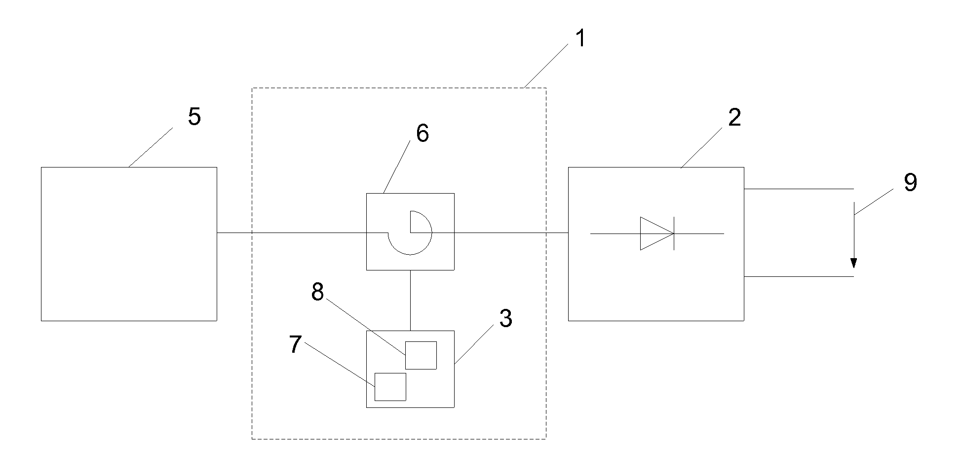
[0048]FIG. 1 shows a control system 1 for controlling a rectifier 2 with an output signal 9 which may be an output voltage or output current to a load (not shown) coupled to the rectifier 2. The rectifier 2 may be a diode rectifier. The load may be an aluminium electrolysis application for example. The control system 1 comprises at least one reactor 6 per phase, means 7 for providing a bias current for controlling the reactor 6 and means 8 for providing a control current for controlling the reactor 6. Preferably, the means 7 and means 8 are stored in a control unit 3 that is coupled to the at least one reactor 6.

[0049]In another embodiment of the present ...


PUM


Abstract

A system and method for controlling a rectifier due to changing operating conditions including at least one reactor per phase connected to the rectifier for providing an input signal, a bias current for controlling the reactor, and a control current for controlling the reactor. The bias current is fixed to a predefined value which is taken as an input signal for providing a control current compensating the difference between the predefined value of the bias current and a start value defining a start point of the linear operating range of the reactor.

Description

FIELD OF THE INVENTION[0001]The present invention relates to a control system for controlling a rectifier. Further, the present invention relates to a method of controlling a rectifier. In particular, the present invention relates to a control system for controlling a diode rectifier.BACKGROUND OF THE INVENTION[0002]A rectifier is known to convert an alternating voltage or current signal into a direct voltage or current signal. It is used in a large field of applications and industrial processes.[0003]The controlling of an output voltage of a rectifier is usually done by the following approach: For coarse regulation of the output voltage of the rectifier, a transformer with on-load tap changers (OLTC) is used. For the fine regulation of the output voltage, saturable reactors are used which are coupled to the rectifier for controlling the rectifier. It is common practice in prior art that the controlling of a reactor is implemented by two current circuits: One bias circuit and one co...

Claims


Application Information

Patent Timeline
Patent Type & Authority Applications(United States)
IPC IPC(8): H02M7/06
CPCH02M7/06
Inventor ACKERET, ALEXANDERGILOMEN, MICHALAUWRENS, WYNAND MARTHINUS
Owner ABB (SCHWEIZ) AG
Why Eureka
Try Eureka