
Swivel Mounting Bracket

A mounting bracket and rotating technology, applied in the direction of supporting machines, connecting components, pins, etc., can solve the problems of complex fixing structure and fixing method, low supporting capacity of the mounting bracket, long construction time, etc., and achieve simple and rapid reset, Convenience and speed of construction and the effect of reducing construction costs

Active Publication Date: 2019-03-29
汉殷ENC株式会社 +2
View PDF8 Cites 0 Cited by
  • Summary
  • Abstract
  • Description
  • Claims
  • Application Information

AI Technical Summary

Problems solved by technology

[0003] However, the existing mounting bracket must be tightened in conjunction with the nut to prevent the main body of the mounting bracket from shaking, and the mounting bracket will also shake up and down because the diameter of the mounting bracket is less than the diameter of the perforation if the nut is loosened a little. The degree of opening advances into the hole of the building
Then, there are the following problems: the fixing structure and fixing method of fixing the mounting bracket on the outer wall of the building are complicated, and the required construction time is long
[0004] In addition, the larger the piercing diameter, the more labor and time are required for the piercing work, but the supporting capacity of the mounting bracket will be lower and the efficiency will be significantly reduced
[0005] In addition, since the building exterior is installed vertically on the mounting bracket, the mounting bracket sags due to the weight of the building exterior, so it is structurally fragile and not conducive to safety.
[0006] In addition, when it is necessary to remove the mounting bracket when the position of the mounting bracket is wrong during work, it is difficult to remove the mounting bracket that has already been constructed, so a lot of labor and labor such as cutting the mounting bracket with a cutter or bending the mounting bracket with a hammer are required. time

Method used


Image

  • Swivel Mounting Bracket
  • Swivel Mounting Bracket
  • Swivel Mounting Bracket

Examples


Embodiment Construction

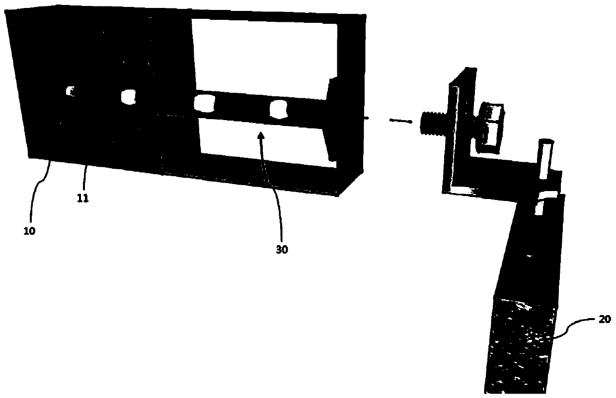
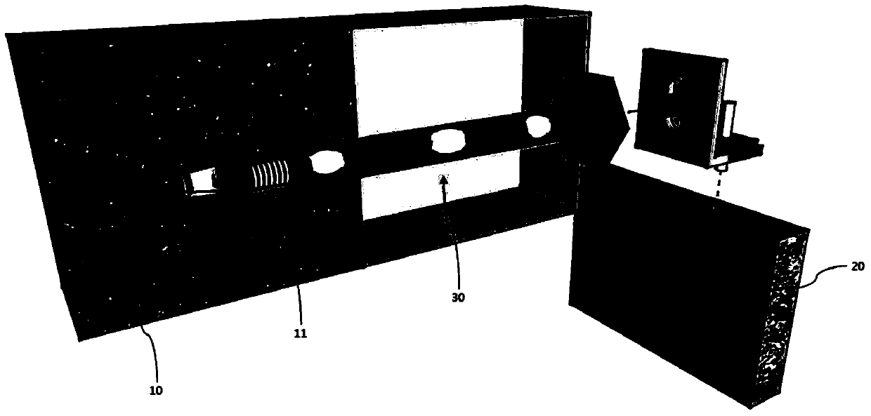
[0057] Hereinafter, some embodiments of the present invention will be described in detail with reference to illustrative drawings. The reference symbols are attached to the components in each figure, and the same symbols are used as far as possible even if the same components are marked on other figures. In addition, in describing the embodiments of the present invention, if it is judged that a specific description of a related well-known structure or function will hinder the understanding of the embodiments of the present invention, the detailed description thereof will be omitted.

[0058] In addition, terms such as first, second, A, B, (a), (b) and the like may be used in describing constituent elements of the embodiments of the present invention. The terminology is used only to distinguish its constituent elements from other constituent elements, and the nature, order, sequence, etc. of the constituent elements will not be limited by the terminology. When it is stated tha...


PUM


Abstract

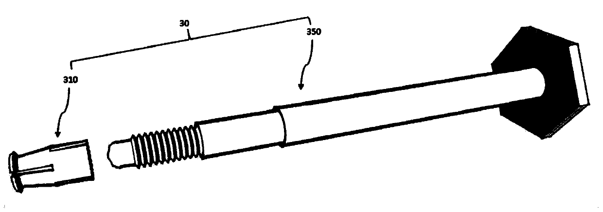
The invention relates to a rotary type mounting bracket which is inserted into a hole formed in a building for being fixed, is projected towards the outer side of the building, and is used for fixing exterior decorative parts and the like of the building. The rotary type mounting bracket comprises a bracket part and a supporting rod, wherein the bracket part is inserted into the hole of the building, and then is expanded and fixed; the supporting rod is combined to the bracket part, is fixed to the hole of the building and is projected towards the outer side of the building; the supporting rod comprises a combination part, an inner main body part, a blocking part, an outer main body part and a rotary fixing part from the inside, wherein the combination part is combined to the bracket part through a screw, and the bracket part is expanded; the inner main body is inserted into the hole of the building in a gap-free tight clinging mode; the blocking part is supported in a hole inlet of the building, so that shaking of the supporting rod is prevented; the outer main body part is projected towards the outer part of the hole of the building; the diameter of the rotary fixing part is greater than that of the outer main body part; and the supporting rod can be rotated, and is combined with exterior decorative parts and the like, combined to the supporting rod, of the building to support. According to the rotary type mounting bracket, after the hole of the building is inserted into the supporting rod which is combined with the bracket part, the supporting rod only needs to rotate for fixing, so that the following effects are provided: convenient and quick construction, and cut-down construction cost.

Description

technical field [0001] The present invention relates to a rotary set anchor, that is, a rotary set anchor that can be quickly and firmly fixed to a hole in a building by only rotating. Background technique [0002] When the exterior part is installed on a building, a hole is generally formed on the building, and after the installation bracket is inserted into the hole for fixing, the building exterior part is installed on the installation bracket. [0003] However, the existing mounting bracket must be tightened in conjunction with the nut to prevent the main body of the mounting bracket from shaking, and the mounting bracket will also shake up and down because the diameter of the mounting bracket is less than the diameter of the perforation if the nut is loosened a little. The degree of opening advances into the hole of the building. Subsequently, there are the following problems: the fixing structure and fixing method for fixing the mounting bracket on the outer wall of t...

Claims


Application Information

Patent Timeline
Patent Type & Authority Patents(China)
IPC IPC(8): F16M13/02F16B13/04
CPCF16B13/04F16M13/02
Inventor 李源雨李相吉
Owner 汉殷ENC株式会社
Learn More