Rotary compressor

A compressor and rotary shaft technology, applied in the field of rotary compressors, can solve problems such as existing limitations, and achieve the effects of preventing excessive compression, reducing indication loss, and reducing collision or wear

Active Publication Date: 2019-11-29
LG ELECTRONICS INC
View PDF7 Cites 3 Cited by
  • Summary
  • Abstract
  • Description
  • Claims
  • Application Information

AI Technical Summary

Problems solved by technology

[0015] However, there is a limit to preventing overcompression of the refrigerant even by bypassing, and even if the diameter of the discharge port is increased, the

Method used


Image

  • Rotary compressor
  • Rotary compressor
  • Rotary compressor

Examples


Embodiment Construction

[0041] Hereinafter, the rotary compressor of the present invention will be described in further detail with reference to the drawings.

[0042] In this specification, unless the context clearly dictates otherwise, the singular expression includes multiple expressions.

[0043] In addition, in the process of describing the embodiments disclosed in the present invention, when it is judged that detailed descriptions of related known technologies will confuse the gist of the embodiments disclosed in the present invention, detailed descriptions of the known technologies are omitted.

[0044] It should be understood that the drawings are only used to help understand the embodiments disclosed in the specification of this book. The technical ideas disclosed in this specification are not limited to the drawings. The scope of the present invention includes the spirit and technical scope of the present invention. All changes, equivalents and substitutes.

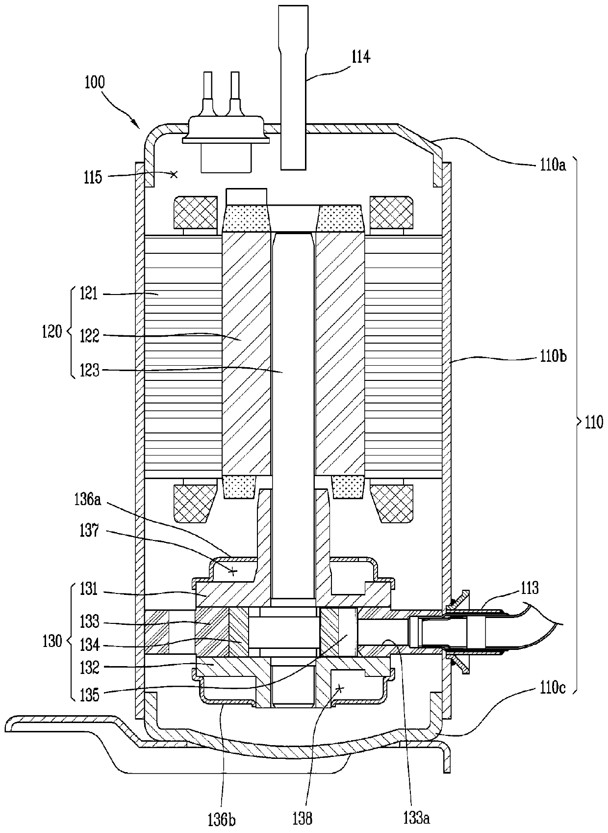
[0045] figure 1 It is a cross-sectional...


PUM


Abstract

The present invention relates to a compressor comprising: a driving motor; a rotary shaft; a main bearing and a sub bearing fixed to a case, and provided along the rotary shaft; a cylinder fixedly provided between the main bearing and the sub bearing, accommodating a refrigerant in the center portion thereof, and having a suction port and a discharge port respectively formed in the radial direction; a roller of which one side is positioned inside the cylinder so as to come in contact with the inner peripheral surface of the cylinder, and which rotates together with the rotary shaft so as to form a compression space inside the cylinder; and at least two vanes insertively provided in the roller, and protruding by the rotation of the roller so as to divide the compression space into a suctionchamber and a compression chamber while coming in contact with the inner peripheral surface of the cylinder, wherein a discharge port groove, which is formed to expand the end portion of the discharge port and increases the flow rate of the compressed refrigerant, is formed at one side of the inner peripheral surface of the cylinder.

Description

Technical field [0001] The present invention relates to a rotary compressor which compresses and discharges a refrigerant drawn into a compression space of a cylinder. Background technique [0002] Compressors are used in vapor compression refrigeration cycles such as refrigerators or air conditioners. According to the method by which the refrigerant is sucked into the compression chamber, the compressor can be divided into an indirect suction method and a direct suction method. [0003] The indirect suction method is a method in which the refrigerant circulating in the refrigeration cycle flows into the internal space of the compressor casing and is sucked into the compression chamber. Unlike the indirect suction method, the direct suction method is a method in which the refrigerant is directly sucked into the compression chamber. The indirect suction method can be called a low pressure compressor, and the direct suction method can be called a high pressure compressor. [0004] In ...

Claims


Application Information

Patent Timeline
IPC IPC(8): F04C18/344F04C29/12F04C28/26
CPCF04C18/344F04C28/26F04C29/12F04C29/124F04C2240/50
Inventor 姜胜敏辛镇雄卢基律
Owner LG ELECTRONICS INC
Why Eureka
Try Eureka