Screw vacuum pump

A screw vacuum pump and screw technology, applied in the direction of pumps, pump components, rotary piston pumps, etc., can solve the problems of mutual contact between rotors, and achieve the effects of reducing reverse ventilation, reducing noise generation, and reducing building volume

Active Publication Date: 2013-01-16
LEYBOLD HERAEUS GMBH & CO KG
View PDF10 Cites 8 Cited by
  • Summary
  • Abstract
  • Description
  • Claims
  • Application Information

AI Technical Summary

Problems solved by technology

However, screw rotors mounted in a floating manner must have short rotors, because othe...

Method used


Image

  • Screw vacuum pump
  • Screw vacuum pump

Examples


Embodiment Construction

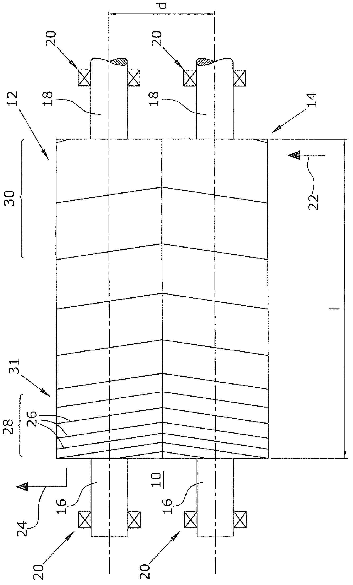
[0017] two in figure 1 The screw rotor shown in is arranged in a pump casing not shown. A pump chamber 10 is formed by the pump housing, in which two screw rotors 12 , 14 are arranged. The two screw rotors have shaft shoulders 16 , 18 on both sides, which are each rotatably mounted in the pump housing via bearing elements 20 . To drive the two screw rotors 12 , 14 , the shaft shoulder 18 or alternatively the shaft shoulder 16 is usually connected directly or via a gear to the drive motor. The second screw rotor is driven by the same drive motor via a corresponding toothing (not shown), so that the two screw rotors 12 , 14 are synchronized with each other and rotate in opposite directions. Suction of the medium to be conveyed takes place on the suction side (arrow 22 ) and discharge of the medium takes place on the pressure side (arrow 24 ) via the screw rotor.

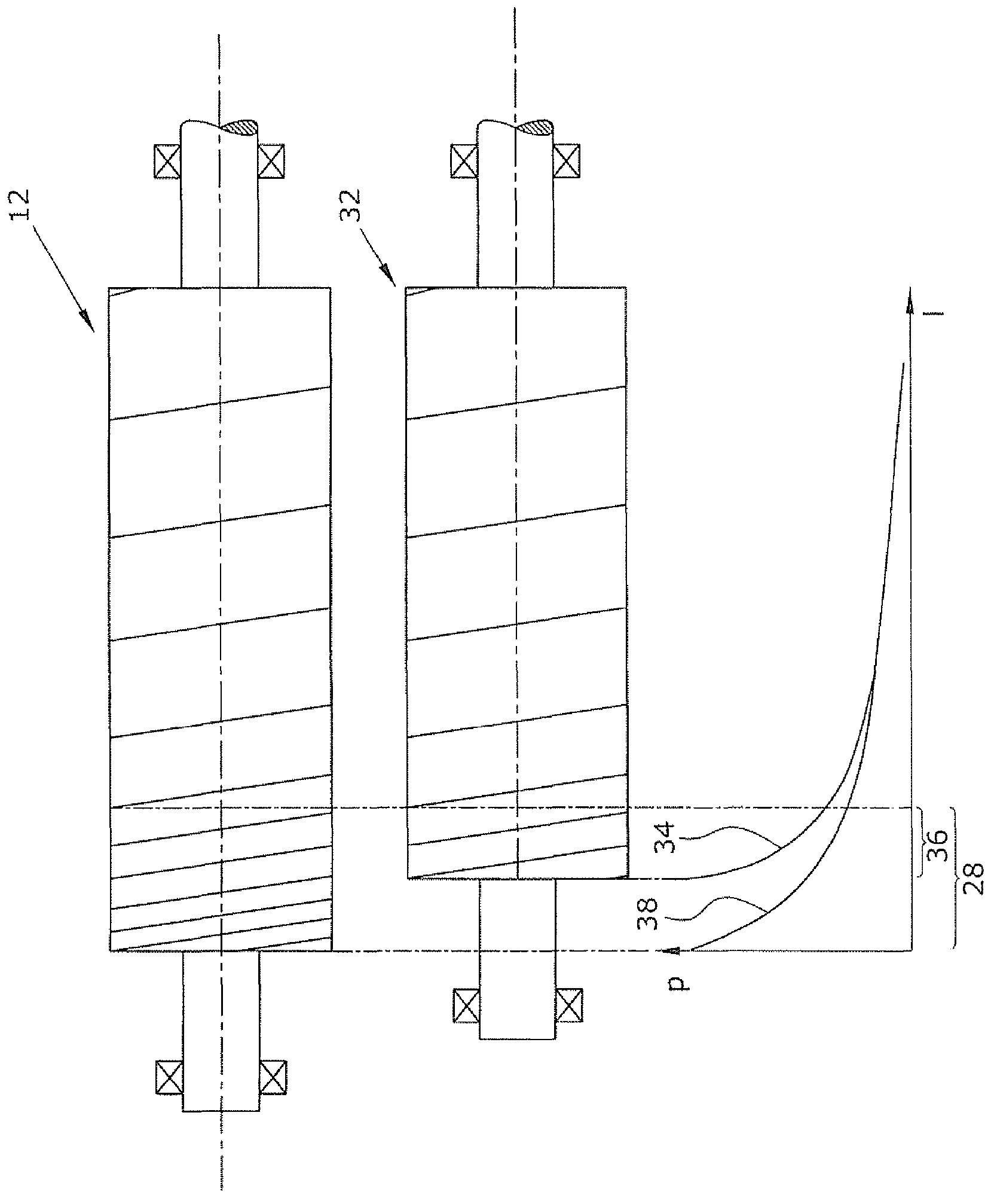
[0018] The pitch of the screw rotor is indicated by an obliquely running line 26 . from figure 1 As can be seen...


PUM


Abstract

The invention relates to a screw vacuum pump comprising screw rotors (12, 14) disposed in a suction chamber (10). The screw rotors (12, 14) are each supported by means of two bearing elements (20) in the pump housing and comprise a ratio of rotor length (I) to rotor axis spacing (d) that is greater than 3.0. The screw rotors (12, 14) further comprise a variable pitch, at least 7 turns, and an integral compression ratio of at least 4.5. The pitch after half of the turns is less than twice the pitch on the pressure side rotor outlet (24).

Description

technical field [0001] The invention relates to a screw vacuum pump. Background technique [0002] Screw vacuum pumps have two screw rotors in a pump chamber formed by the pump housing. Screw rotors are usually mounted on both sides and can have differently designed pitch profiles. The rotor can have a symmetrical or asymmetrical tooth profile, as described, for example, in "Wutz", Handbook of Vacuum Technology, 10th Edition, 2010, pages 270-277. Such rotors generally have an internal compression ratio, ie a chamber volume ratio of the chambers on the suction side to the chambers on the pressure side, of less than 4. At high suction pressures, higher compression ratios result in very high power consumption. This requires the use of disproportionately large drive motors (see "Wutz" ibid., p. 276). Furthermore, when the compression is increased, the problem arises that high temperatures occur in the region of the pressure side of the screw rotor. In this case, heat dissip...

Claims


Application Information

Patent Timeline
IPC IPC(8): F04C18/16F04C18/08F04C25/02
CPCF04C2240/20F04C18/084F04C18/16F04C29/04F04C25/02F04C15/06F04C18/00F04C18/02F04C18/08F04C29/00F04C29/025
Inventor 托马斯·德赖费特马格努斯·亚尼茨基彼得·比尔克罗兰德·米勒
Owner LEYBOLD HERAEUS GMBH & CO KG
Why Eureka
Try Eureka