Scroll compressor

A technology of scroll compressors and compression chambers, applied in the field of scroll compressors, can solve problems such as unstable operation of circular scrolls, increased vibration or noise

Active Publication Date: 2015-12-23
LG ELECTRONICS INC
View PDF7 Cites 8 Cited by
  • Summary
  • Abstract
  • Description
  • Claims
  • Application Information

AI Technical Summary

Problems solved by technology

However, on the contrary, the operating point to which the repulsive force of the refrigerant is applied and the operating point to which the reaction force for counteracting the repulsive force is applied are separated from each other in the axial direction, causing increased vibration or noise during operation while the circular scroll Unstable operation problem

Method used


Image

  • Scroll compressor
  • Scroll compressor
  • Scroll compressor

Examples


Embodiment Construction

[0031] Hereinafter, a through-shaft scroll compressor according to the present disclosure will be described in detail based on an embodiment shown in the drawings.

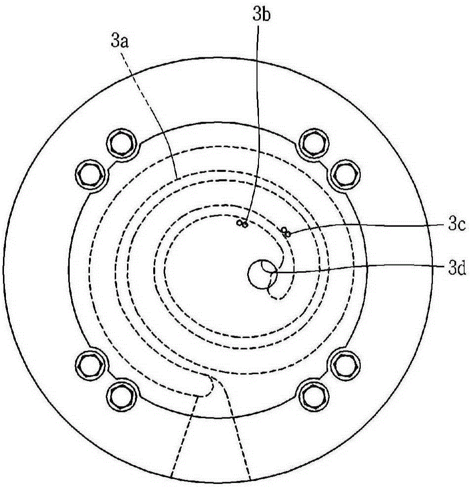
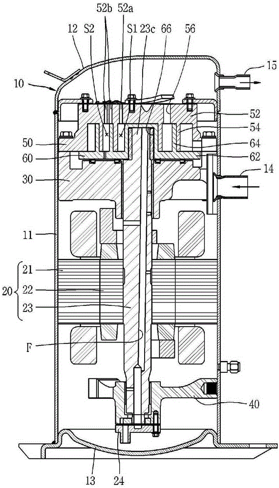
[0032] image 3 To show a longitudinal sectional view of a shaft through scroll compressor according to the present disclosure, Figure 4 to show the basis image 3 The axis of the shaft runs through the plan view of the compression unit in the scroll compressor, and Figure 5 to show and to image 3 The plan view of the split hole communicated with each compression chamber in the scroll compressor by the axis of the shaft.

[0033] As shown in the figure, in the shaft through scroll compressor according to the present embodiment, the driving motor 20 may be installed in the sealed container 10, and the main frame 30 and the subframe 40 may be installed on the upper side and the lower side of the driving motor 20. , the fixed scroll 50 may be fixed and installed on the upper side of the main frame 30 , and the...


PUM


Abstract

According to a scroll compressor associated with the present disclosure, the entire cross-sectional area of bypass holes formed at a compression chamber with a larger volume reduction gradient between the both compression chambers may be formed to be larger than that of bypass holes at the other compression chamber to prevent over-compression at the compression chamber with a larger volume reduction gradient, thereby enhancing the entire efficiency of the compressor.

Description

technical field [0001] The present disclosure relates to a scroll compressor, and more particularly, to a scroll compressor formed to have different volume reduction gradients for two compression chambers. Background technique [0002] A scroll compressor is a compressor in which the orbiting scroll moves relative to the fixed scroll in a state where the fixed wrap of the fixed scroll is engaged with the orbiting wrap of the orbiting scroll. During the orbiting motion, a continuously moving compression chamber is formed between the fixed scroll and the orbiting scroll to suck and compress refrigerant. [0003] The scroll compressor continuously performs suction, compression, and discharge, and thus has superior characteristics in terms of vibration and noise generated during its operation, as compared with other types of compressors. [0004] The operating characteristics of a scroll compressor are determined by the types of its fixed and orbiting scrolls. The fixed and or...

Claims


Application Information

Patent Timeline
Patent Type & Authority Applications(China)
IPC IPC(8): F04C18/02F04C14/26
CPCF04C18/0215F04C18/0261F04C28/26F04C2270/195F04C2270/80F04C2270/86F04C14/26F04C18/02F01C1/0215F01C1/0261F04C15/06F04C18/0246F04C23/008F04C29/12F04C2240/808
Inventor 崔龙揆元仁昊金哲欢
Owner LG ELECTRONICS INC
Why Eureka
Try Eureka