Carrier tape, carrier tape manufacturing apparatus, and method of manufacturing carrier tape

A carrier tape and tape-like technology, which is applied in the directions of packaging, transportation and packaging, packaging item types, etc., can solve the problems of breakage of the punch 202, increase in manufacturing cost, reduction in tensile strength and bending stiffness, etc. Possibility of breakage, improvement of tensile strength, effect of shortening manufacturing process

Active Publication Date: 2012-03-14
MURATA MFG CO LTD
View PDF9 Cites 9 Cited by
  • Summary
  • Abstract
  • Description
  • Claims
  • Application Information

AI Technical Summary

Problems solved by technology

However, there is a problem in that, in order to maintain the strength of the drag box 110, there is also a limit to reducing the thickness of the walls separating the buffers 112, and it is difficult to form the recesses 122 at a small pitch.
In order to convey the base material 120 embedded in the buffer 112, the work of lifting the base material 120 embedded in the buffer 112 is required, so that there is a problem that the manufacturing process cannot be shortened and the manufacturing cost increases.
In addition, since the convex portion 123 is formed on the back surface of the base material 120, when the base material 120 is conveyed, there is a problem that the boundary between the convex portion 123 and the drag box 110 rubs against the boundary and generates dust.
[0011] In addition, in the carrier tape 221 disclosed in Patent Document 2, since the thickness of the base material 220 located directly below the concave portion 222 is thinner than that of the base material 220 at other positions, there is a pull in the longitudinal direction of the base material 220. Tensile strength, bending rigidity decrease such problems
In addition, after the concave portion 222 is formed, the back surface of the base material 220 is still flat, so the depth of the concave portion 222 formed on the surface of the base material 220 cannot be made more than the thickness of the base material 220.
In addition, since the drag box 210 disclosed in Patent Document 2 has the die plate 211 in which the surface on which the base material 220 is placed is formed of a flat surface, when the concave portion 222 is formed with the punch 202, there is the following problem: The material 220 is excessively compressed by the bottom surface of the concave portion 222, and the load applied to the punch 202 itself becomes an overload, thereby there is a possibility that the punch 202 is damaged.

Method used


Image

  • Carrier tape, carrier tape manufacturing apparatus, and method of manufacturing carrier tape
  • Carrier tape, carrier tape manufacturing apparatus, and method of manufacturing carrier tape
  • Carrier tape, carrier tape manufacturing apparatus, and method of manufacturing carrier tape

Examples


Embodiment Construction

[0060] Hereinafter, embodiments of the present invention will be described in detail with reference to the drawings.

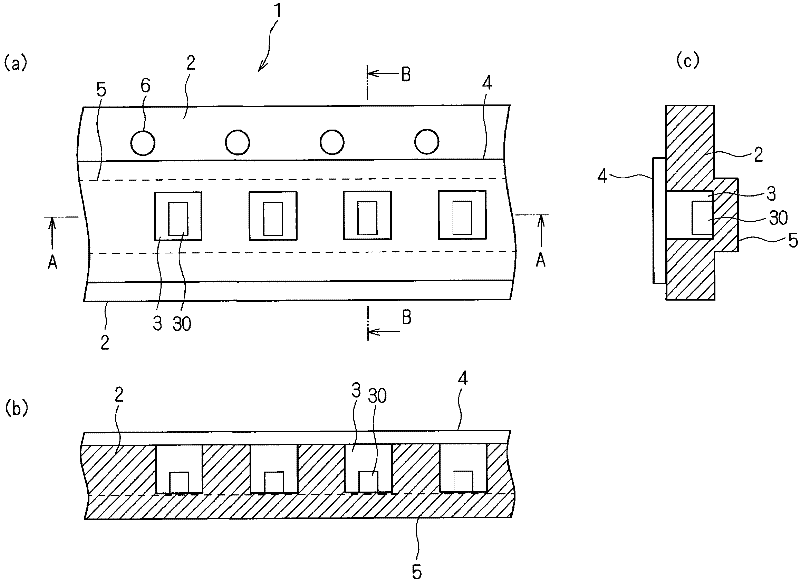
[0061] figure 1 It is a plan view and a cross-sectional view of the carrier tape according to the embodiment of the present invention. figure 1 (a) is a top view of the carrier tape 1, figure 1 (b) is the A-A sectional view of the carrier tape 1, figure 1 (c) is a B-B sectional view of the carrier tape 1 . The carrier tape 1 is a carrier tape composed of a strip-shaped base material 2, and includes a plurality of recesses 3 formed on the surface (one side surface) of the base material 2 for accommodating electronic components 30. Cover 4, which closes the opening of the recess 3; and a protrusion 5, which is formed on the other side of the base along the longitudinal direction of the base 2, and has It spans the length of more than two recesses 3 . Guide holes 6 are provided in the substrate 2 of the carrier tape 1 in parallel with the recesses 3 , an...


PUM

PropertyMeasurementUnit
lengthaaaaaaaaaa
widthaaaaaaaaaa
heightaaaaaaaaaa

Abstract

Provided is acarrier tape with improved tensile strength and flexural rigidity in a longitudinal direction of a base material, including recesses provided at a narrow pitch in one surface of the base material, and manufacturable at reduced cost, as well as to provide an apparatus and a method for manufacturing such a carrier tape. The carrier tape of the present invention is constituted by a strip-shaped base material (2), and includes: a plurality of recesses (3) provided in one surface of the base material (2) and for containing electronic components (30); a covering unit (4) configured to seal openings of the recesses (3); and a projection (5) provided on the other surface of the base material (2) along a longitudinal direction of the base material (2), a length of the projection being such that the projection (5) extends over at least two of the recesses (3).

Description

technical field [0001] The present invention relates to a carrier tape, a carrier tape manufacturing device, and a manufacturing method of the carrier tape, and particularly relates to a carrier tape, a carrier tape, and a carrier tape having a plurality of recesses formed on one side of a base material for accommodating electronic components. Tape manufacturing apparatus and method for manufacturing a carrier tape. Background technique [0002] In an apparatus for mounting electronic components on a circuit board, a carrier tape containing electronic components is used in order to easily supply the electronic components. Patent Document 1 and Patent Document 2 disclose conventional methods of manufacturing carrier tapes. [0003] Patent Document 1 discloses a method of manufacturing a carrier tape by compression-molding a strip-shaped base material between a cope and a drag, wherein the cope has a punch that forms a carrier tape. A plurality of recesses are used to accomm...

Claims


Application Information

Patent Timeline
Patent Type & Authority Applications(China)
IPC IPC(8): B65D73/02B65B15/04
CPCH05K13/0084B29C43/44B65D73/02B65D85/00B65D85/38
Inventor 床井正护清水保弘
Owner MURATA MFG CO LTD
Why Eureka
Try Eureka