
Gate valve with integrated support members

a technology of support member and gate valve, which is applied in the direction of valve details, valve arrangement, lift valve, etc., can solve the problems of fluid leakage, damage to seals, and difficulty in achieving an adequate seal between the gate and the main body structur

Active Publication Date: 2013-03-26
EMERSON VULCAN HLDG LLC
View PDF10 Cites 10 Cited by
  • Summary
  • Abstract
  • Description
  • Claims
  • Application Information

AI Technical Summary

Benefits of technology

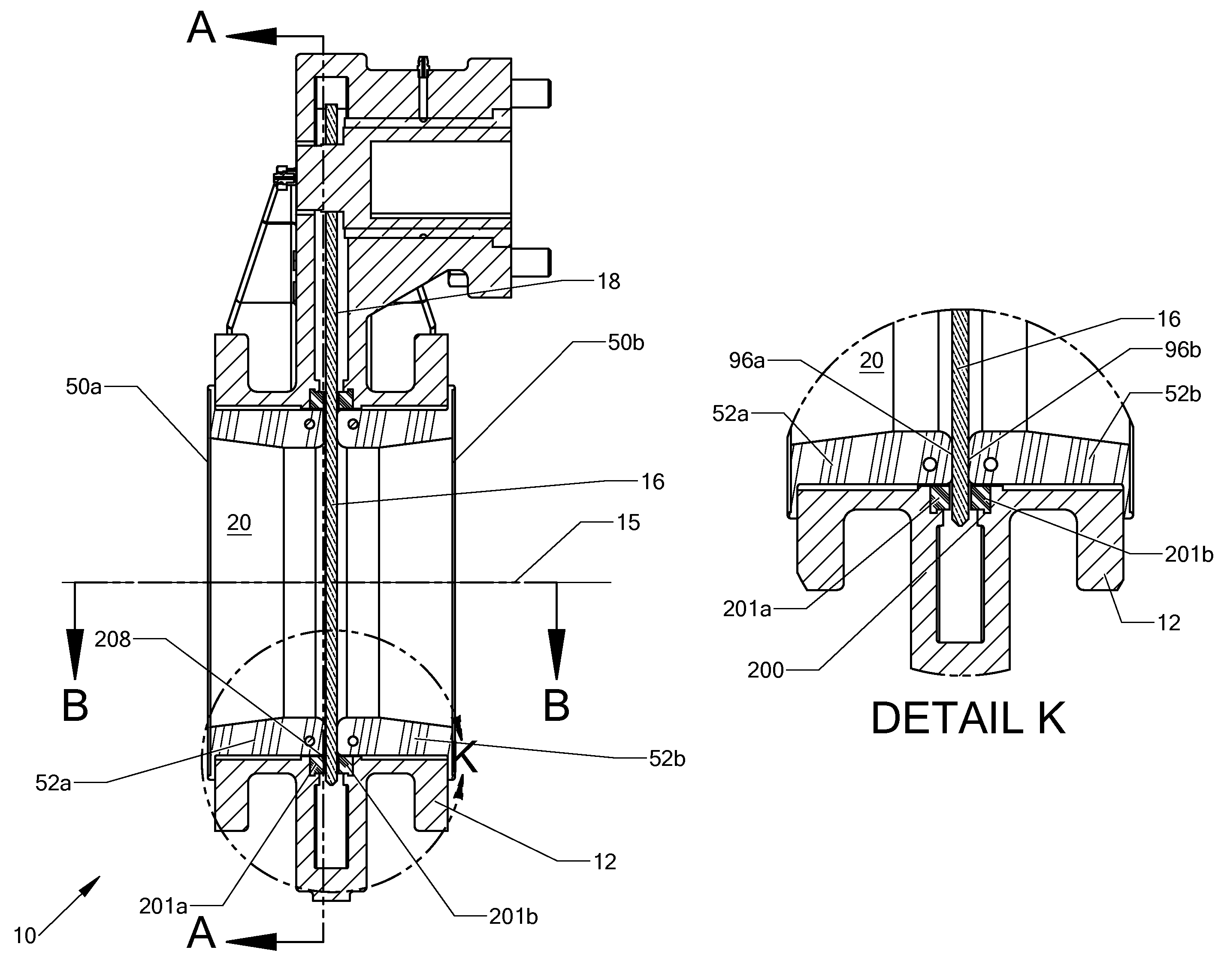
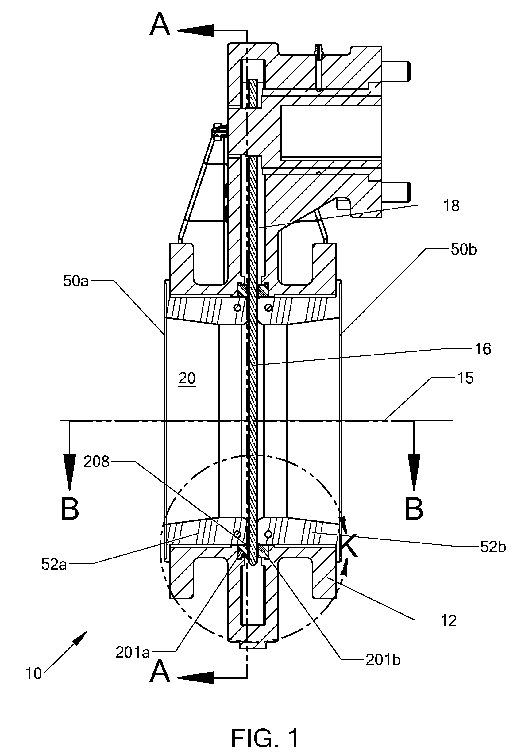
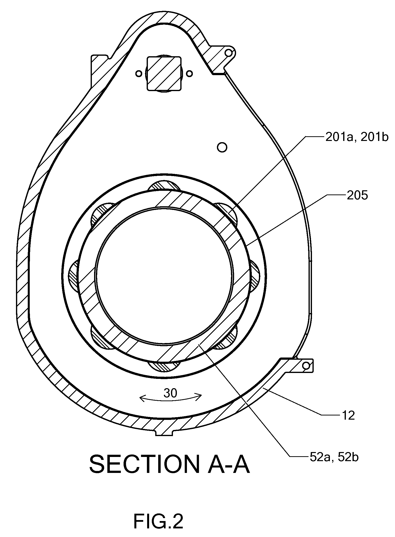
The present invention is about a gate valve that can be moved to control the flow of fluid through a passage. The gate has two sides with a peripheral margin, and the valve has two sets of rigid support members that prevent overcompression of the elastomer sleeves when they engage the gate. The rigid support members facilitate displacement of the elastomer sleeves and ensure proper positioning of the gate within the passage. The technical effect of this invention is to improve the stability and reliability of the gate valve, allowing for safe and reliable control of fluid flow.

Problems solved by technology

For fluids that include a mixture of solids, referred to as a slurry, an adequate seal between the gate and the main body structure can be difficult to achieve.
The solids in such slurries can clog, coat, or damage a seal in many gate valves and thereby allow the fluid to leak.
The solid resilient sleeve units can be difficult to displace when closing the valve because the design does not include a way to eliminate overcompression of the sleeve from the flange-raised face surfaces of the mating conduit, thereby making the valve difficult to operate.
Moreover, pressure against the gate in a valve closed position can displace the resilient sleeve unit on the downstream side and allow a leak between the gate and the upstream resilient sleeve unit.
However, this design requires special tooling and molding of the hub.

Method used


Image

  • Gate valve with integrated support members
  • Gate valve with integrated support members
  • Gate valve with integrated support members

Examples


example 1

[0032]A rotary gate valve, having an eight inch (8 in) opening. Eight support members on one side of the gate were made of UHMW™ having a surface area of 0.62 square inches of surface area on one side, resulting in a total surface area of approximate 5 square inches adjacent to the gate.

example 2

[0033]A rotary gate valve, having an eight inch (8 in) opening was configured. Eight support members on one side of the gate were made of PTFE having a surface area of 0.62 square inches of surface area on one side, resulting in a total surface area of approximate 5 square inches adjacent to the gate.

example 3

[0034]A 14 inch version of the Clarkson linear-actuated knife gate valve was configured with the present invention. The support members were made of UHMW™. The valve was configured with a quantity of four gate supports on each side of the gate. Each support member had a surface area (adjacent to the gate) of approximately 10 square inches, with a total of approximately 36 square inches per side adjacent to the gate.

[0035]Analysis revealed that yield strength of the compositions resulted in the UHMW™ deforming less than the PTFE. Ryton™ deformed the least. As such, a greater surface area of PTFE is needed than the other two compositions, with more PTFE surface area needed than for the Ryton™.


PUM


Abstract

A gate valve has support members that are attached to a main body structure of the gate valve adjacent to the valve gate opening. These support members are affixed on both sides of the valve gate opening radially around a gate sleeve.

Description

TECHNICAL FIELD[0001]The present invention relates to gate valves having integrated support members along the periphery of the passage within the main body structure of the valve to decrease degradation of an elastomer seal.BACKGROUND OF THE INVENTION[0002]Gate valves are used to control the flow of various fluids carried inside tubular conduits or pipes. A gate valve typically includes a main body structure with a passage positioned between and coupling a pair axially-aligned conduits that are bolted to opposite sides of the main body structure. A flat, fluid-impermeable gate with a pair of opposed, substantially planar faces is slidable into the passage through a slot in the main body structure to selectively occlude the passage and thereby close the valve.[0003]Gate valves that are used to control the flow of fluids include a seal between the gate and the main body structure to prevent the fluid from leaking, either from the valve or across it when closed. For fluids that include...

Claims


Application Information

Patent Timeline
Patent Type & Authority Patents(United States)
IPC IPC(8): F16K3/00
CPCF16K3/0227F16K3/02F16K3/30F16K3/314
Inventor NGUYEN, VIET
Owner EMERSON VULCAN HLDG LLC
Learn More