Rail surface air drying machine

An air dryer and rail surface technology, which is applied in locomotives, track cleaning, construction, etc., can solve the problems of insufficient locomotive traction, difficulty in achieving punctual arrival, and reduced running speed, so as to eliminate potential safety hazards and improve operating efficiency. , the effect of improving the running speed

Inactive Publication Date: 2019-12-03
丁红卫
View PDF6 Cites 3 Cited by
  • Summary
  • Abstract
  • Description
  • Claims
  • Application Information

AI Technical Summary

Problems solved by technology

[0003] At present, the measures to prevent locomotives from idling and sliding are still based on sand spreading, supplemented by reducing traction. The new locomotive adopts a computer to weaken the traction current, and still uses sand to prevent locomotives from idling and sliding, but the traction of the locomotive cannot be fully utilized. The speed is reduced and it is difficult to achieve punctual arrival. Therefore, in view of the above status quo, it is urgent to develop a rail surface air dryer to overcome the shortcomings in current practical applications

Method used


Image

  • Rail surface air drying machine
  • Rail surface air drying machine

Examples


Embodiment 1

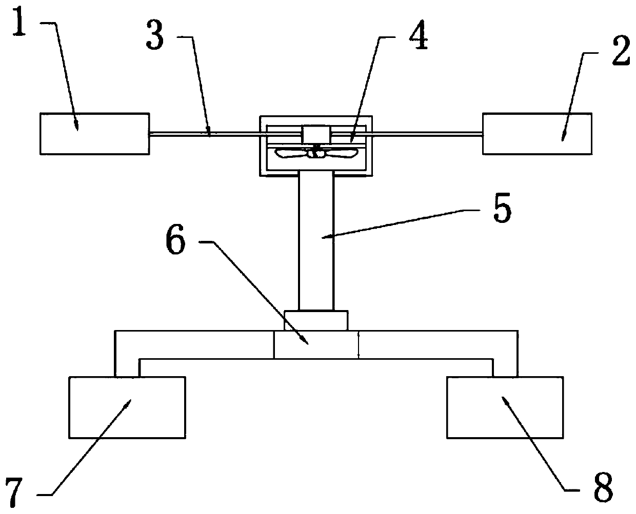
[0024] see Figure 1~2 , in an embodiment of the present invention, a rail surface air dryer includes a first switch 1 and a second switch 2, both of the first switch 1 and the second switch 2 are electrically connected to the fan 4 through a wire 3, and the fan 4 The output end is fixedly connected with an air outlet pipe 5, and the other end of the air outlet pipe 5 is fixedly connected with a two-position changeover switch 6, and the output ends on both sides of the two-position changeover switch 6 are respectively connected to the front and rear of the car body through pipes. The first electric heating box 7 and the second electric heating box 8 at both ends are connected. By setting the fan 4 and the electric heating box, the rail surface can be made dry and clean, and a dry and clean rail surface can be provided for the locomotive, so that the locomotive can always be At a stable and peaceful running speed, it is no longer affected by rain, snow and unclean rail surface,...

Embodiment 2

[0026] In this embodiment, the first switch 1 and the second switch 2 are respectively arranged in the control rooms at the front and rear ends of the train.

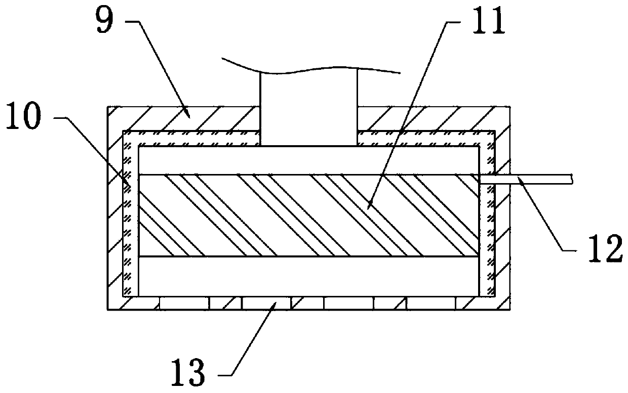
[0027] In this embodiment, the first electric heating box 7 includes a box body 9, a thermal insulation layer 10 and a heater, the box body 9 is fixedly connected and arranged at the bottom of the train body, and the inner side of the box body 9 is fixedly connected with a thermal insulation layer. layer 10, a heater fixedly connected to the box body 9 is arranged inside the heat preservation layer 10, and several purge ports 13 are arranged at the bottom end of the box body 9.

[0028] In this embodiment, the heater is electrofusion 11 .

[0029] In this embodiment, the electric fuse 11 located in the first electric heating box 7 is electrically connected to the first switch 1 through the first power line 12 .

[0030] In this embodiment, the electric fuse 11 located in the second electric heating box 8 is electricall...


PUM


Abstract

The invention relates to the technical field of train accessory machinery, particularly to a rail surface air drying machine, which includes a first switch and a second switch, wherein both the firstswitch and the second switch are electrically connected with a fan through wires; an air outlet pipe is fixedly connected with the output end of the fan, and the other end of the air outlet pipe is fixedly connected with two position change-over switches; the output ends on the two sides of the two position change-over switches are respectively connected with a first heater case and a second heater case through pipelines. According to the invention, through arranging the fan and the heater cases, the rail surface is changed to be dry and clean to enable the engine in traction to be in a stableand steady running speed without being affected by rain and snow and unclean steel rain surface, as a result, the running speed is improved, idle sliding of the engine is avoided, and running behindschedule and slope stopping and slowing down are fundamentally avoided.

Description

technical field [0001] The invention relates to the technical field of train auxiliary machinery, in particular to a rail surface air dryer. Background technique [0002] At present, the traction force of locomotives used on railways is far greater than the adhesion force. When the traction force is greater than the adhesion force, the locomotive will idling and slide, especially when the traction train encounters dirty rail surfaces or rainy and snowy weather during operation. Idling coasting, when the locomotive is idling and gliding, the wheels of the locomotive rotate at high speed, the traction force even drops to zero, and the running speed decreases, causing the train to be delayed, and in serious cases, it will cause parking accidents, which will have a very bad impact on the safety and punctuality of railway transportation, and bring serious damage Economic losses. Because the wheels of the locomotive rotate at a high speed when idling, the wheels of the locomotive...

Claims


Application Information

Patent Timeline
Patent Type & Authority Applications(China)
IPC IPC(8): B61C15/08E01H8/08E01H8/10
CPCB61C15/08E01H8/08E01H8/105
Inventor 丁红卫
Owner 丁红卫
Why Eureka
Try Eureka