Telescopic cantilever and telescopic cantilever type plate turnover machine comprising same

A turning machine and cantilever type technology, applied in the direction of conveyor objects, transportation and packaging, furnaces, etc., can solve the problem of inability to turn over large-sized glass, and achieve the effect of avoiding vibration

Active Publication Date: 2019-12-03
中建材智能自动化研究院有限公司
View PDF14 Cites 1 Cited by
  • Summary
  • Abstract
  • Description
  • Claims
  • Application Information

AI Technical Summary

Problems solved by technology

[0006] In order to solve the above technical problems, the present invention provides a retractable cantilever type turning machine that is not limited by the conveying height, so as to overcome the problem that the cantilever of the glass turning machine in the prior art is limited by the conveying height and cannot turn over large-sized glass. question

Method used


Image

  • Telescopic cantilever and telescopic cantilever type plate turnover machine comprising same
  • Telescopic cantilever and telescopic cantilever type plate turnover machine comprising same
  • Telescopic cantilever and telescopic cantilever type plate turnover machine comprising same

Examples


Embodiment 1

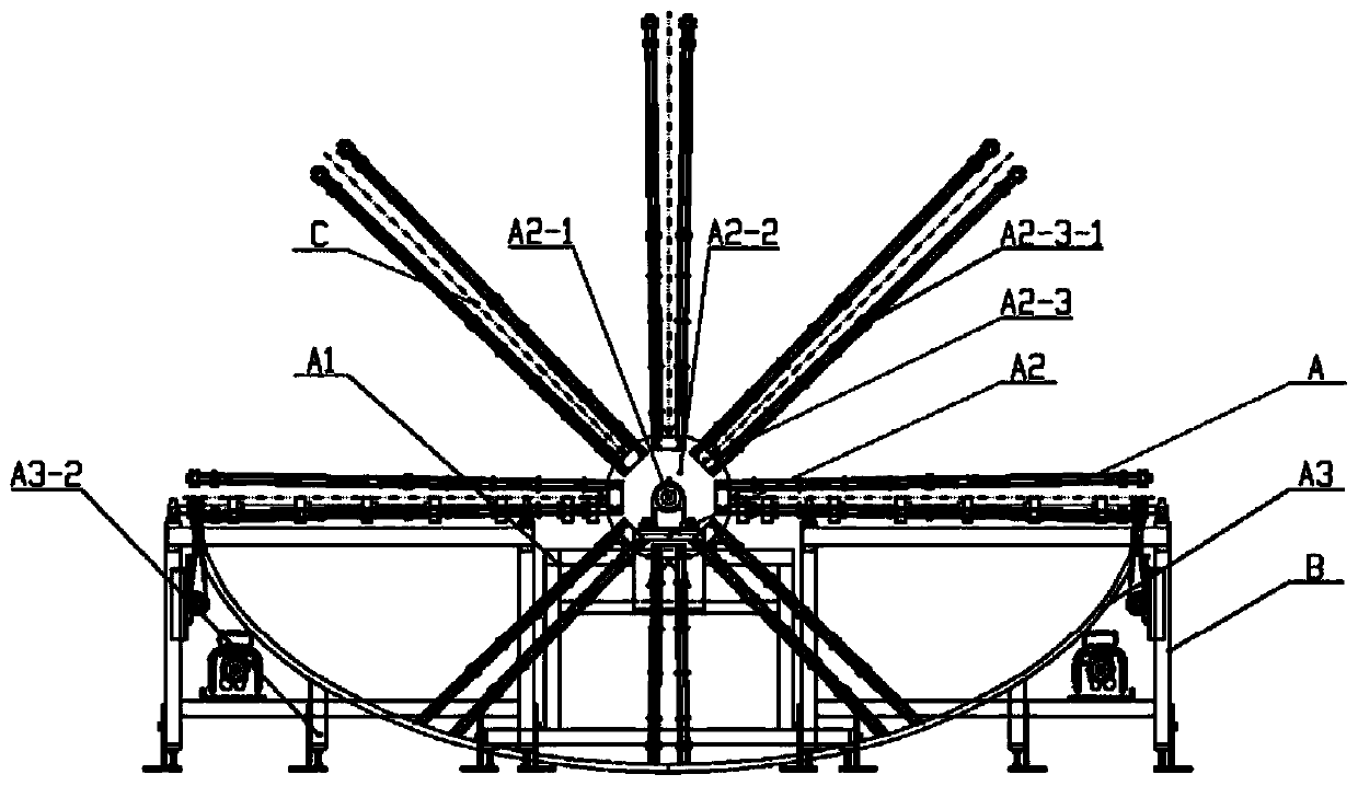
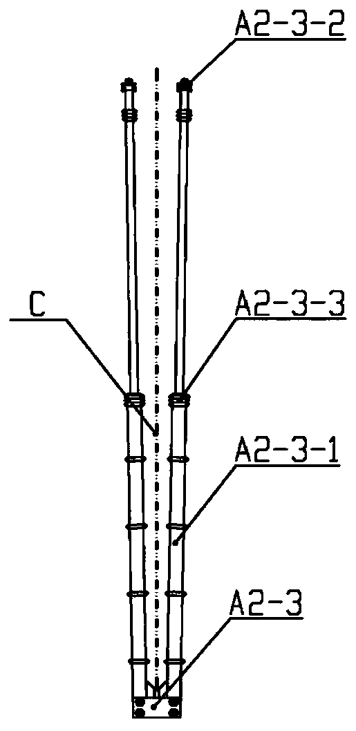
[0032] Such as figure 1 As shown, this embodiment provides a sun-wheel type glass turning machine, which includes a clamping cantilever assembly A2-3, and the clamping cantilever assembly A2-3 includes a fixed plate and two clamping cantilevers A2-3-1, The two clamping arms A2-3-1 are respectively arranged on one side of the fixing plate.

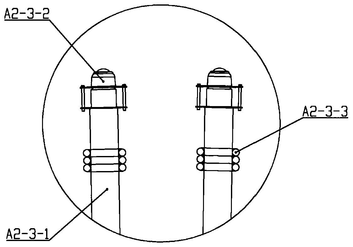
[0033] In this specific example, if Figure 1-5 As shown, there is an included angle of 1 degree between the two clamping cantilevers A2-3-1. A plurality of O-shaped rubber rings A2-3-3 are sheathed on the clamping cantilever A2-3-1. A V-shaped block is also arranged on the fixed plate between the two clamping arms A2-3-1, and a V-shaped groove is arranged on the side of the V-shaped block away from the fixed plate. A guide wheel is arranged in the V-shaped groove. The clamping arm A2-3-1 is a support rod. A bull's-eye universal ball A2-3-2 is provided at the end of the support rod away from the fixed plate.

Embodiment 2

[0035] The present invention also provides a retractable cantilever type turning machine comprising the retractable cantilever of Embodiment 1, including a frame A1, a turning device A2, an arc guide rail A3 and a driving mechanism; the turning device A2 is arranged on the On the frame A1, the arc-shaped guide rail A3 is arranged on the frame A1 and directly below the turning device A2, and the driving mechanism is used to drive the turning device A2.

[0036] The overturning device A2 includes a mandrel on which four rotary disks A2-2 are arranged, and each of the rotary disks A2-2 is provided with eight clamping cantilever assemblies A2-3 in the circumferential direction One end of the clamping cantilever assembly A2-3 away from the fixing plate is slidably disposed in the arc-shaped guide rail A3.

[0037] Establish a space Cartesian coordinate system with the axis of the mandrel A2-1 as the Z axis, the original length of the clamping cantilever A2-3-1 is L, and the conveyi...


PUM


Abstract

The invention discloses a telescopic cantilever and a telescopic cantilever type plate turnover machine comprising the same, and relates to the technical field of glass deep processing, the turnover machine comprises a rack and a turnover device body arranged on the rack. The turnover machine comprises a mandrel, a plurality of rotary discs are arranged on the mandrel at equal intervals, a plurality of clamping cantilever sets are arranged on the circumferential side wall of each rotary disc, each clamping cantilever assembly comprises two clamping cantilevers which are symmetrically arranged,a working gap used for clamping glass exists in the middle of each clamping cantilever assembly, and each clamping cantilever is of a telescopic structure. An arc-shaped guide rail is further arranged below the clamping cantilever assembly, wherein in the process that the clamping cantilever rotates from the opening in one end to the opening in the other end, the compressed shortest length is smaller than or equal to the conveying elevation. According to the plate turnover machine, the problem that the maximum plate turnover size of the plate turnover machine is limited by the conveying elevation is solved, and under the condition of the same conveying elevation, the plate turnover machine can achieve plate turnover of glass with the larger size.

Description

technical field [0001] The invention relates to the technical field of glass deep processing, in particular to a telescopic cantilever and a telescopic cantilever type turning machine comprising the same. Background technique [0002] In the field of glass deep processing, the original glass is generally processed by various processes on the deep processing production line. At present, most of the glass deep processing processes involve glass turning, so there is at least one dedicated for glass deep processing on the glass deep processing production line. The equipment for glass turning, that is, glass turning machine. [0003] At present, the glass turning machines used in the glass deep processing production line are generally divided into two types, one is the circular turning machine, and the other is the sun wheel turning machine. What the present invention will discuss is the sun wheel turning machine Generally speaking, this kind of glass turning machine is composed...

Claims


Application Information

Patent Timeline
Patent Type & Authority Applications(China)
IPC IPC(8): B65G49/06
CPCB65G49/063B65G49/067Y02W30/40
Inventor 叶林伟夏东劼王宇轩张鼎冯达贤杨乐韩玮竺肖君
Owner 中建材智能自动化研究院有限公司
Why Eureka
Try Eureka