Air return energy-saving device for fan

An energy-saving device and return air technology, which is applied to the components of the pumping device for elastic fluid, mechanical equipment, machines/engines, etc., can solve the problems of filter plate installation tilt, increase installation strength, and complicated installation, etc., to achieve Easy to replace the feet, fast installation, not easy to loose effect

Pending Publication Date: 2019-12-03
江苏金天雪莲生态保养有限公司
View PDF0 Cites 0 Cited by
  • Summary
  • Abstract
  • Description
  • Claims
  • Application Information

AI Technical Summary

Problems solved by technology

[0002] The fan coil return air box is mainly installed at the air outlet end of the fan. Its main function is to return air. It is a measure taken to save energy consumption and ensure the working effect of the fan. There is a lot of dust attached to the surface, which affects work efficiency
[0003] When the existing fan coil return air box is in use, it isolates the inside and outside of it through the filter plate at the end to prevent the external dust from entering the inside of the box, and at the same time filter the dust in the air to ensure the cleanliness of the air However, when the existing filter isolation plate is installed, a large number of screws are used to fasten it around, which makes the installation complicated and increases the installation strength. At the same time, the filter plate is prone to installation inclination during the fastening process , thus affecting the filtering effect of the equipment, for this reason, the present invention proposes a return air energy-saving device for fans

Method used


Image

  • Air return energy-saving device for fan
  • Air return energy-saving device for fan
  • Air return energy-saving device for fan

Examples


Embodiment 1

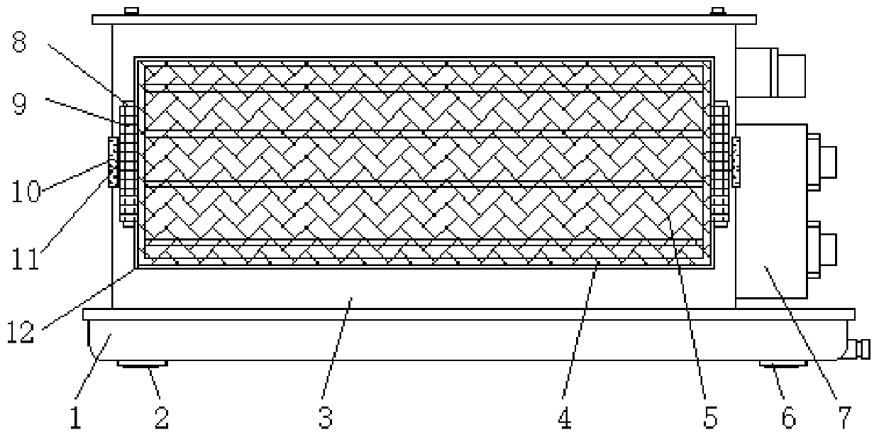
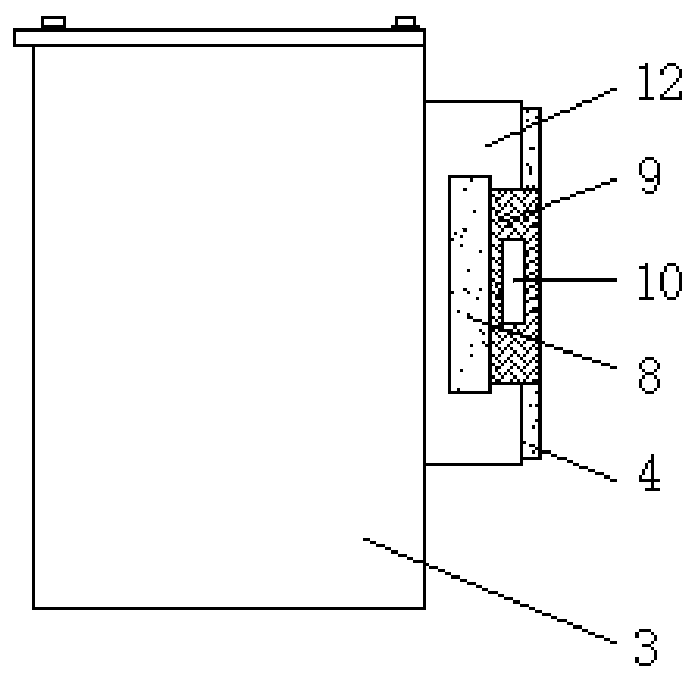
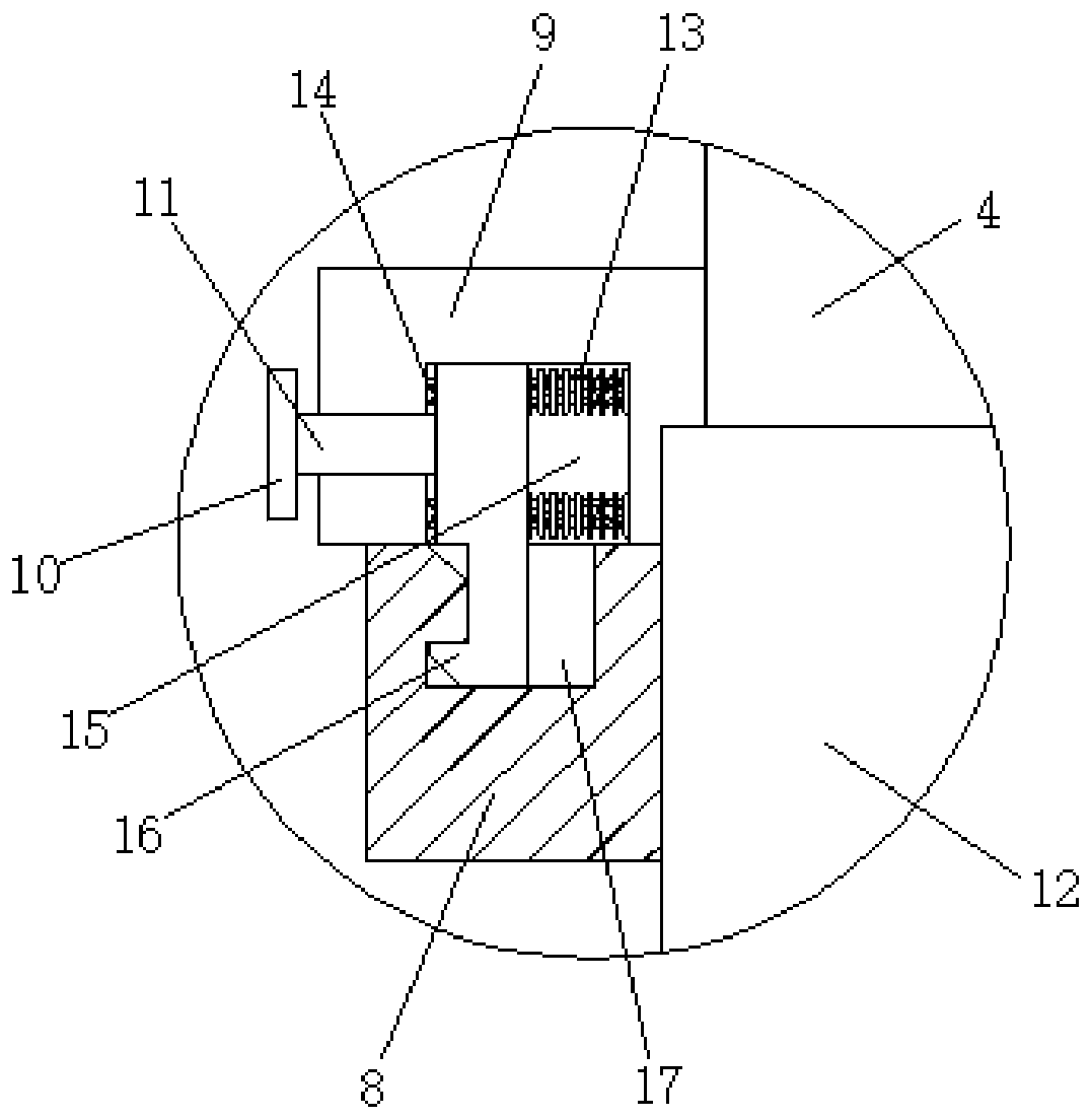
[0025] see Figure 1 to Figure 5 , the present invention provides a technical solution: a return air energy-saving device for fans, including a return air box 3, an installation shell 12 is connected to the surface of one end of the return air box 3, and a grid frame 4 is arranged at the end of the installation shell 12, and the inside of the grid frame 4 is connected There is a filter isolation plate 5, and installation blocks 9 are fixed on both sides of the net frame 4, and a storage tank 15 is provided at the bottom of the installation block 9, and a fixing plate 16 is arranged inside the storage tank 15, and the fixing plate 16 can be quickly snapped into the fixing groove 17 of the fixing block 8, so as to quickly install and limit the filter isolation plate 5, and avoid the traditional installation method being too complicated and prone to deviation. Both sides of the outer wall of the installation shell 12 are connected with fixing blocks 8, Through the designed fixed ...

Embodiment 2

[0027] see Figure 1 to Figure 6 , the present invention provides a technical solution: a return air energy-saving device for fans, including a return air box 3, an installation shell 12 is connected to the surface of one end of the return air box 3, and a grid frame 4 is arranged at the end of the installation shell 12, and the inside of the grid frame 4 is connected There is a filter isolation plate 5, and installation blocks 9 are fixed on both sides of the net frame 4, and a storage tank 15 is provided at the bottom of the installation block 9, and a fixing plate 16 is arranged inside the storage tank 15, and the fixing plate 16 can be quickly snapped into the fixing groove 17 of the fixing block 8, so as to quickly install and limit the filter isolation plate 5, and avoid the traditional installation method being too complicated and prone to deviation. Both sides of the outer wall of the installation shell 12 are connected with fixing blocks 8, Through the designed fixed ...


PUM


Abstract

The invention discloses an air return energy-saving device for a fan. The device comprises an air return box, a mounting shell is connected to the surface of one end of the air return box, a net rackis arranged at the end of the mounting shell, a filtering isolation plate is connected to the inner side of the net rack, mounting blocks are fixed to the two sides of the net rack, storage grooves are formed in the bottoms of the mounting blocks, fixing plates are arranged in the storage grooves, and fixing blocks are connected to the two sides of the outer wall of the mounting shell; according to the invention, the designed fixing plates can be quickly clamped into the fixing grooves of the fixing blocks, so the filtering isolation plate can be quickly mounted and limited, and the situationthat a traditional mounting mode is too complex and prone to deviation is avoided; by means of the designed fixing blocks, the designed fixing blocks and the mounting blocks are attached to each other, so mounting of the filtering isolation plate is limited, and springs and the designed fixing plates are mounted and supported by means of the designed sliding rods.

Description

technical field [0001] The invention belongs to the technical field of fan energy saving, and in particular relates to a return air energy saving device for a fan. Background technique [0002] The fan coil return air box is mainly installed at the air outlet end of the fan. Its main function is to return air. It is a measure taken to save energy consumption and ensure the working effect of the fan. There is a lot of dust attached to the surface, which affects work efficiency. [0003] When the existing fan coil return air box is in use, it isolates the inside and outside of it through the filter plate at the end to prevent the external dust from entering the inside of the box, and at the same time filter the dust in the air to ensure the cleanliness of the air However, when the existing filter isolation plate is installed, a large number of screws are used to fasten it around, which makes the installation complicated and increases the installation strength. At the same tim...

Claims


Application Information

Patent Timeline
Patent Type & Authority Applications(China)
IPC IPC(8): F04D29/60F04D29/40F04D29/66F04D29/70
CPCF04D29/403F04D29/601F04D29/668F04D29/703
Inventor 田蜜箱郝振华
Owner 江苏金天雪莲生态保养有限公司
Why Eureka
Try Eureka