Eureka AIR delivers breakthrough ideas for toughest innovation challenges, trusted by R&D personnel around the world.

A projection equipment mounting bracket capable of quick disassembly and lifting control

A technology for projection equipment and mounting brackets, which is applied in the direction of mechanical equipment, machines/brackets, projection devices, etc., can solve the problems of projection equipment dropping, long disassembly time, and poor versatility, so as to avoid falling, short disassembly time, Versatile effect

Active Publication Date: 2021-10-15
深圳市云杰科技文化有限公司
View PDF8 Cites 0 Cited by
  • Summary
  • Abstract
  • Description
  • Claims
  • Application Information

AI Technical Summary

Problems solved by technology

[0006] The purpose of the present invention is to provide a projection equipment mounting bracket that can realize quick disassembly and lifting control, so as to solve the problem that the existing projection equipment on the market proposed by the above-mentioned background technology is generally fixed on the installation by screws. , when installing and disassembling, it is necessary to disassemble all the screws before the projection device can be removed from the mounting bracket. The disassembly time is long, and the problem of the projection device falling is easy to occur, which is not conducive to the rapid disassembly of the projection device. Moreover, due to the differences in the size of projection equipment of different brands and models, it is inconvenient to fix the projection equipment, and a special machine is required, which has the problem of poor versatility

Method used


Image

  • A projection equipment mounting bracket capable of quick disassembly and lifting control
  • A projection equipment mounting bracket capable of quick disassembly and lifting control
  • A projection equipment mounting bracket capable of quick disassembly and lifting control

Examples


Embodiment Construction

[0028] Based on the embodiments of the present invention, all other embodiments obtained by persons of ordinary skill in the art without making creative efforts belong to the protection scope of the present invention.

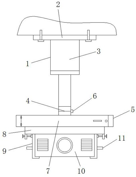
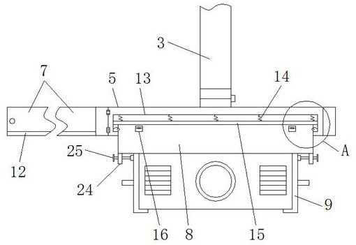
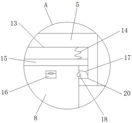
[0029] see Figure 1-9 , the present invention provides a technical solution: a projection equipment mounting bracket capable of quick disassembly and lifting control, including a mounting bracket main body 1, a fixing seat 2, an electric telescopic device 3, a rotating shaft 4, a mounting frame 5, a screw-on Nut 6, fixed plate 7, mounting base 8, mounting plate 9, projection device 10, handle 11, support block 12, mounting groove 13, spring 14, push plate 15, first limit block 16, second limit block 17 , reset rotating shaft 18, rotation groove 19, first limit groove 20, second limit groove 21, slide groove 22, slide block 23, support plate 24, adjustment rod 25, bolt 26 and installation port 27, installation bracket main body 1 The top of the top is provided...


PUM


Abstract

The invention discloses a projection setting mounting bracket capable of quick disassembly and lifting control, comprising a mounting bracket main body, an electric telescopic device, a rotating shaft, a tightening nut, projection equipment, a handle, a reset rotating shaft and bolts, the mounting bracket The top of the main body is provided with a fixed seat, and an electric telescopic device is provided under the fixed seat, and the lower end of the electric telescopic device is connected with the mounting frame through a rotating shaft, and a tightening nut is arranged on the rotating shaft at the same time, and the front of the mounting frame The side is provided with a fixed plate, and the lower part of the inner side of the fixed plate is provided with a support block, the inner side of the installation plate is connected with the projection equipment through bolts, and the lower end surface of the installation frame is provided with an installation port. The projection setting installation bracket that can realize quick disassembly and lifting control can realize the rapid installation of projection equipment on the installation frame, and does not need to dismantle a large number of bolts, the disassembly time is short, and different types of projection equipment can be installed and fixed , strong versatility.

Description

technical field [0001] The invention relates to the technical field of projection equipment, in particular to a projection equipment mounting bracket capable of quick disassembly and lifting control. Background technique [0002] Projector is a common electronic device in people's life. It is widely used in teaching and conference rooms. It can project video images on the projection screen arranged on the wall. It is generally installed directly on the top of the wall in the room. Its shape is generally a rectangular structure. [0003] However, the existing projection equipment has the following problems during use; [0004] 1. The existing projection equipment is generally fixed on the installation with screws during installation. When installing and disassembling, it is necessary to remove all the screws before the projection equipment can be removed from the mounting bracket. The disassembly takes a long time. And it is easy to cause the problem of projection equipment...

Claims


Application Information

Patent Timeline
Patent Type & Authority Patents(China)
IPC IPC(8): F16M11/04F16M11/10F16M11/28F16M13/02G03B21/54
CPCF16M11/041F16M11/10F16M11/28F16M13/027G03B21/54
Inventor 蒋小娟
Owner 深圳市云杰科技文化有限公司
Why Eureka
Eureka Blog
Learn More