Braking device for a mechanism driven by an electric motor
What is Al technical title?
Al technical title is built by PatSnap Al team. It summarizes the technical point description of the patent document.
A technology of braking device and motor, applied in the direction of brake type, deceleration device parts, mechanical equipment, etc., can solve the problems of large electric braking energy loss, easy aging, long use time of spring, etc., to achieve small energy loss, prevent The effect of heating and strengthening the fixing effect
Active Publication Date: 2019-12-06
TAIZHOU SUMING VALVES CO LTD
View PDF5 Cites 0 Cited by
Summary
Abstract
Description
Claims
Application Information
AI Technical Summary
This helps you quickly interpret patents by identifying the three key elements:
Problems solved by technology
Method used
Benefits of technology
Problems solved by technology
[0004] Aiming at the deficiencies in the prior art, the purpose of the present invention is to provide a braking device of a motor-driven mechanism to solve the problem that the friction force of the electromagnetic brake depends on the spring to achieve enhancement. The spring is easy to age after a long service time and reduces the friction force. Braking energy loss is large, unable to meet the needs of the existing market
Method used
Image
Click on the blue label to locate the original text in one second.
Reading with bidirectional positioning of images and text.
Examples
Embodiment Construction
[0025] In order to make the technical means, creative features, objectives and effects of the present invention easy to understand, the present invention will be further explained below in conjunction with specific embodiments.
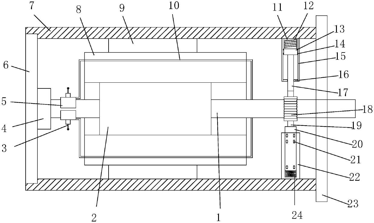
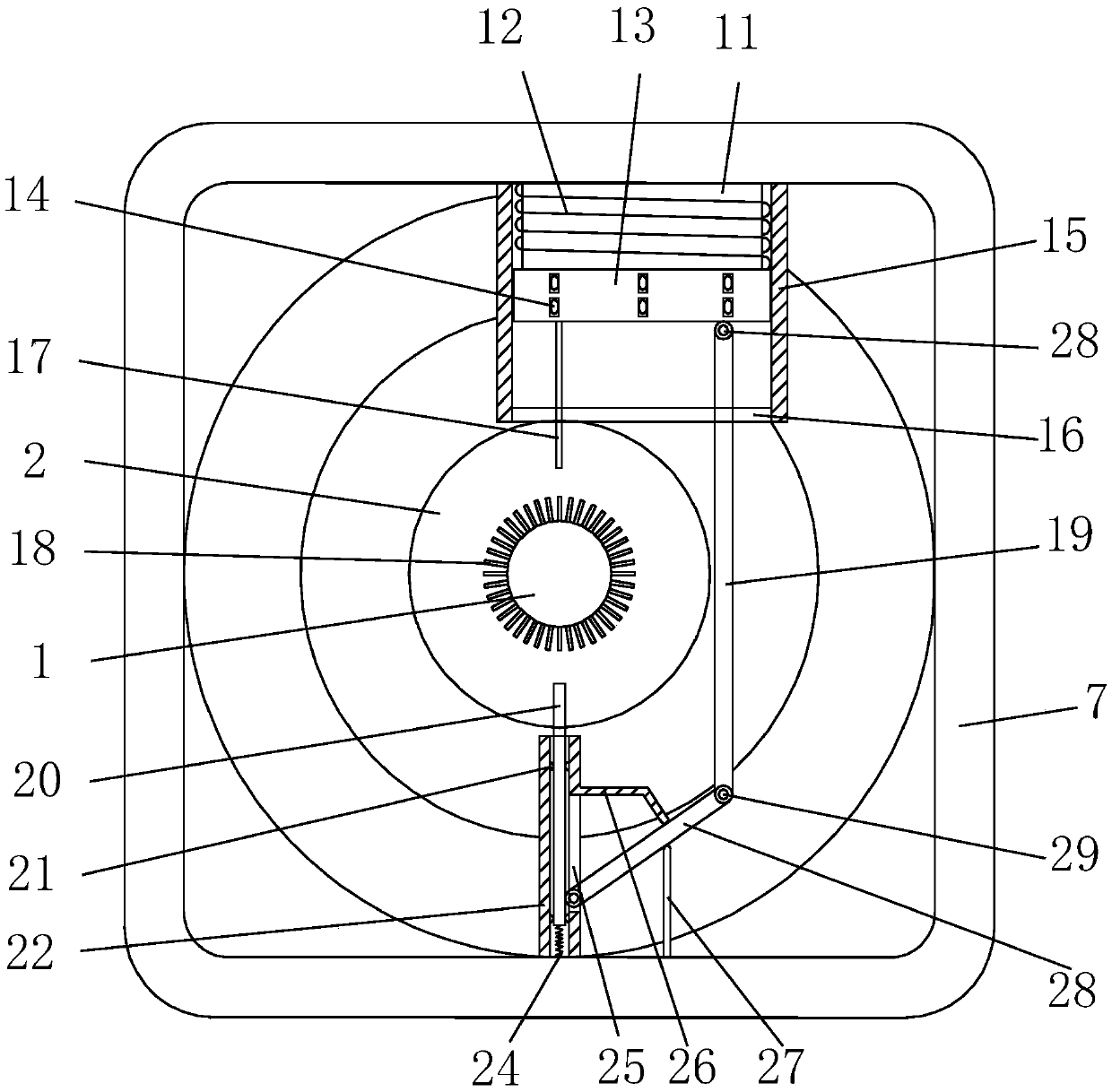
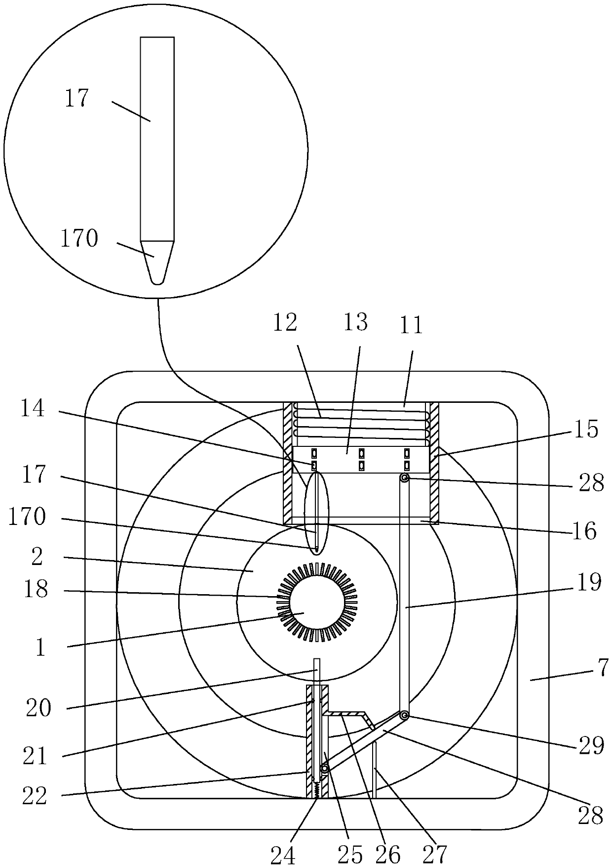
[0026] See Figure 1-Figure 6 , The present invention provides a technical solution for a brake device for a motor-driven mechanism: its structure includes a rotating shaft 1, a rotor core 2, a brush 3, a bearing 4, a commutator 5, a rear end cover 6, a housing 7, and a stator winding 8. Stator core 9, winding coil 10, core 11, coil 12, armature 13, roller I 14, upper guide rail 15, limit block 16, upper brake pad 17, blade 18, connecting rod I 19, lower brake pad 20, The roller II 21, the lower rail 22, the front end cover 23, the spring 24, the slot 25, the baffle 26, the vertical plate 27, the connecting rod II 28, the hinge 29, the rear end of the housing 7 is embedded with the rear end cover 6, the The front end cover 23 is arranged at the front en...
PUM
Abstract
The invention discloses a braking device for a motor driven mechanism. The braking device has a structure that includes a rotating shaft, a rotor core, electric brushes, a bearing, a commutator segment, a rear end cover, a housing, a stator winding, a stator core, a winding coil, an iron core, a coil, an armature, rollers I, an upper guide rail, a limit block, an upper brake pad, a blade, a connecting rod I, a lower brake pad, rollers II, a lower guide rail, a front end cover, a spring, a slotting, a baffle, a vertical plate, connecting rods II, and a hinge. The rear end cover is embedded to the rear end of the housing. The front end cover is arranged at the front end of the housing and connected with the housing through a bolt. The rotating shaft penetrates through the front end cover. The rotating shaft is arranged on the central axis of the housing. According to the invention, the braking device for the motor driven mechanism is capable of quickly braking the rotating shaft throughthe upper brake pad and the lower brake pad, with small energy loss and with no need to worry about the aging of the spring, the spring at the bottom of the lower brake pad enables the lower brake padto rise more quickly, and through the acceleration of the rising process, the rotating shaft can be quickly braked.
Description
Technical field [0001] The invention is a brake device of a motor-driven mechanism, belonging to the field of motor brake devices. Background technique [0002] After the motor is cut off the power supply, it takes a period of time (or distance) to rotate by inertia, and the hook of the crane or the hanging basket of the hoist in production requires accurate positioning; the main shaft of the universal milling machine is required to stop quickly; the elevator is stopped after a sudden power failure Need safety protection and accurate positioning control...etc. All of these need to brake the driving motor. The so-called brake is to give the motor a torque opposite to the direction of rotation to make it stop quickly (or limit its speed). There are generally two types of braking methods: mechanical braking and electrical braking. [0003] Common methods of mechanical braking: electromagnetic brake, electromagnetic brake, electromagnetic brake is the brake wheel by the friction plat...
Claims
Application Information
Patent Timeline
Application Date:The date an application was filed.
Publication Date:The date a patent or application was officially published.
First Publication Date:The earliest publication date of a patent with the same application number.
Issue Date:Publication date of the patent grant document.
PCT Entry Date:The Entry date of PCT National Phase.
Estimated Expiry Date:The statutory expiry date of a patent right according to the Patent Law, and it is the longest term of protection that the patent right can achieve without the termination of the patent right due to other reasons(Term extension factor has been taken into account ).
Invalid Date:Actual expiry date is based on effective date or publication date of legal transaction data of invalid patent.