
Planetary reducer output shaft non-windowing structure

A technology of planetary reducer and output shaft, applied in mechanical equipment, transmission parts, belts/chains/gears, etc. problems, to achieve the effect of superior practical performance, easy operation and novel design

Pending Publication Date: 2019-12-03
江苏摩多利传动机械制造有限公司
View PDF7 Cites 0 Cited by
  • Summary
  • Abstract
  • Description
  • Claims
  • Application Information

AI Technical Summary

Problems solved by technology

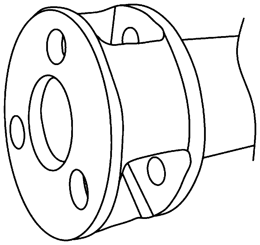
The existing planetary reducer mainly includes the ring gear casing, the input shaft, the sun gear keyed to the input shaft, the planetary gear meshing with the sun gear, and the output shaft for installing the planetary gear. At present, the output shaft of the planetary reducer is a windowed structure, such as figure 1 As shown, the output shaft is slotted to facilitate the assembly of the planetary gear. However, such a window structure is difficult to process, high in cost, and it is difficult to guarantee the accuracy of the process. Moreover, the planetary reducer is not easy to assemble and disassemble, and is easy to be damaged. Other components that cooperate with it do not have positive technical effects, are not practical, and have deficiencies, which cannot meet the needs of development

Method used


Image

  • Planetary reducer output shaft non-windowing structure
  • Planetary reducer output shaft non-windowing structure
  • Planetary reducer output shaft non-windowing structure

Examples


Embodiment Construction

[0021] In order to make the technical means, creative features, goals and effects achieved by the present invention easy to understand, the present invention will be further described below in conjunction with specific illustrations.

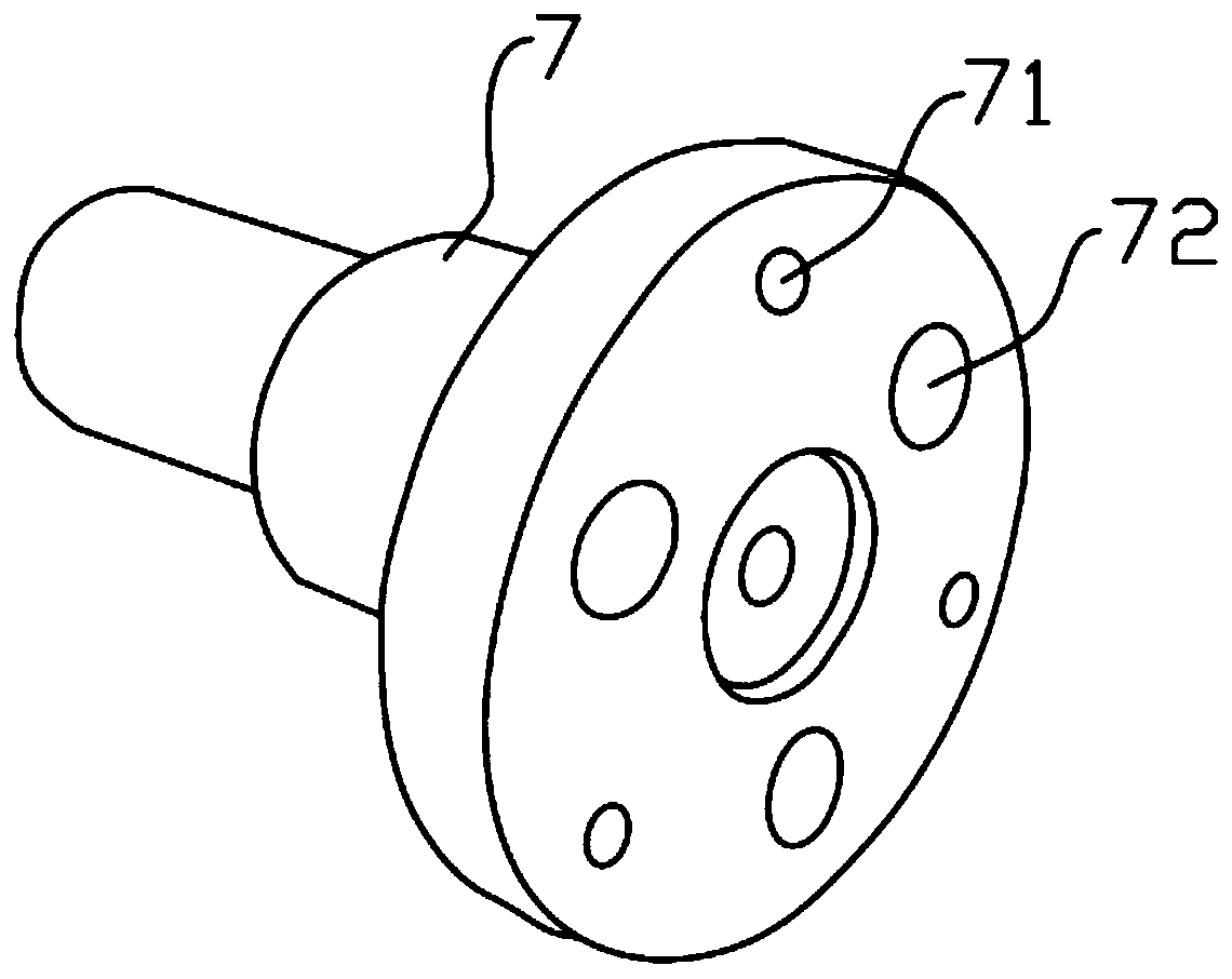
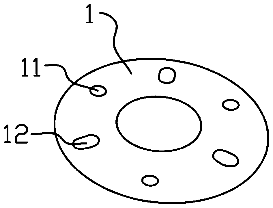
[0022] The structure of the output shaft of the planetary reducer without opening the window is as follows: figure 2 , image 3 , Figure 4 , Figure 5 , Figure 6 As shown, the planetary carrier is a cylindrical structure without windows, and the end faces of the planetary carrier are provided with through holes 72 and screw holes 71 respectively. The mandrel 6 is connected with the needle roller 5 planetary wheel 4, the inner wall of the mandrel 6 is provided with an internal thread, the end face of the planetary wheel 4 has a wear-resistant gasket 3, and the wear-resistant gasket 3 is a circular hole structure facing the internal thread, and the wear-resistant The outer end surface of the grinding pad is attached with a large gasket 1, a...


PUM


Abstract

The invention discloses a planetary reducer output shaft non-windowing structure, which includes an output shaft; a planet carrier is integrally formed on the output shaft; the planet carrier is of acylindrical structure without a window. A through hole and a screw hole are respectively formed in the end surface of the planet carrier; the interior of the through hole is connected with a planet wheel through a tight-fit mandrel; internal threads are formed in the inner wall of the mandrel; wear-resistant gaskets are placed on the end faces of the planet wheels. A large gasket is attached to the outer end surface of the wear-resistant gasket; kidney-shaped holes and through holes are respectively formed in the surface of the large gasket; the position of the kidney-shaped hole corresponds to the position of the internal thread; the positions of the through holes correspond to those of the screw holes; fastening screws are arranged between the kidney-shaped holes and the internal threads. The locking screws are arranged between the through holes and the screw holes, the large gasket is fastened in the screw holes in the surface of the output shaft through the screws. The structure iseasy to manufacture, wherein the planet wheel is convenient to mount and dismount due to the fact that the windowing-free structure is connected with the large gasket through the screws, meanwhile, other matched parts are prevented from being damaged during mounting and dismounting, so that the planet wheel is a very good innovative scheme and has market popularization prospects.

Description

technical field [0001] The invention relates to the planetary reducer technology, in particular to a structure without a window for the output shaft of the planetary reducer. Background technique [0002] Planetary reducers are used in a wide range of industrial occasions, and can also be used as supporting components for lifting, excavation, transportation, construction and other industries. The existing planetary reducer mainly includes the ring gear casing, the input shaft, the sun gear keyed to the input shaft, the planetary gear meshing with the sun gear, and the output shaft for installing the planetary gear. At present, the output shaft of the planetary reducer is a windowed structure, such as figure 1 As shown, the output shaft is slotted to facilitate the assembly of the planetary gear. However, such a window structure is difficult to process, high in cost, and it is difficult to guarantee the accuracy of the process. Moreover, the planetary reducer is not easy to ...

Claims


Application Information

Patent Timeline
IPC IPC(8): F16H57/023F16H57/08
CPCF16H57/023F16H57/08F16H2057/0235
Inventor 李柏君李泽民
Owner 江苏摩多利传动机械制造有限公司
Learn More