Power system cooling device

A technology for cooling devices and power systems, which is applied to transmission parts, gear lubrication/cooling, belts/chains/gears, etc., and can solve problems such as insufficient flow controllability of oil cooling devices

Active Publication Date: 2019-12-03
GUANGZHOU AUTOMOBILE GROUP CO LTD
View PDF20 Cites 2 Cited by
  • Summary
  • Abstract
  • Description
  • Claims
  • Application Information

AI Technical Summary

Problems solved by technology

[0004] Based on this, it is necessary to provide a power system cooling device for the problem of insufficient flow controllability of the oil cooling device driven by dual oil pumps

Method used


Image

  • Power system cooling device
  • Power system cooling device
  • Power system cooling device

Examples


Embodiment Construction

[0031] In order to facilitate the understanding of the present application, the present application will be described more fully below with reference to the relevant drawings. Preferred embodiments of the application are shown in the accompanying drawings. However, the present application can be embodied in many different forms and is not limited to the embodiments described herein. On the contrary, the purpose of providing these embodiments is to make the understanding of the disclosure of the application more thorough and comprehensive.

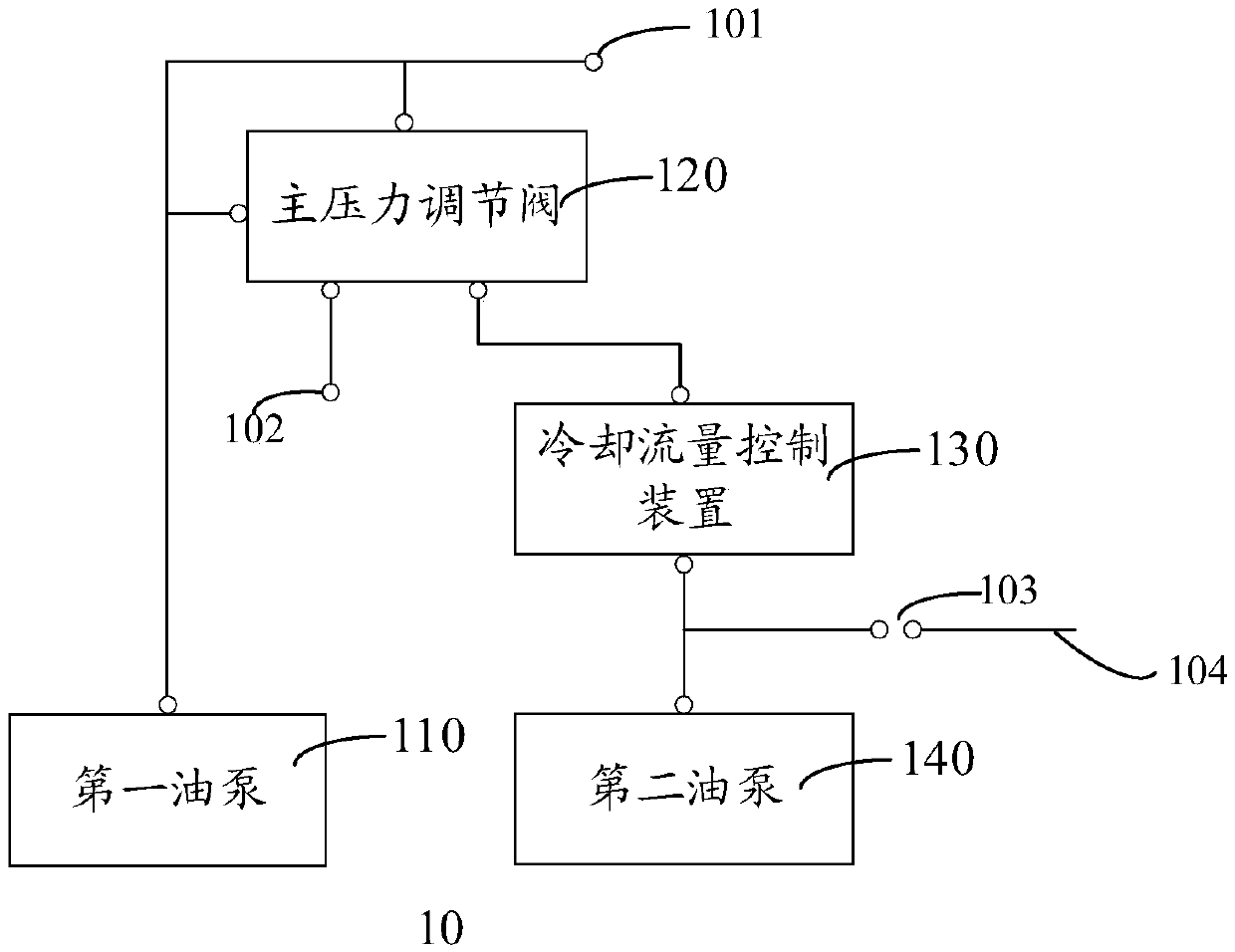
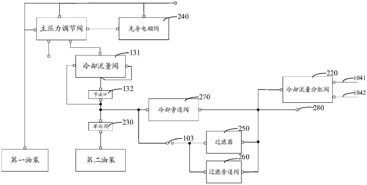
[0032] Please refer to figure 1 , is a schematic structural diagram of a power system cooling device 10 according to an embodiment of the present application, including:

[0033] The first oil pump 110 , the main pressure regulating valve 120 , the cooling flow control device 130 and the second oil pump 140 .

[0034] The output end of the first oil pump 110 is connected to the input end of the main pressure regulating valve 120, the fee...


PUM


Abstract

A power system cooling device comprises a first oil pump, a main pressure regulating valve, a cooling flow control device and a second oil pump. The output end of the first oil pump is connected withthe input end of the main pressure regulating valve, the feedback end of the main pressure regulating valve and the actuator connecting port, the cooling output end of the main pressure regulating valve is connected with the input end of the cooling flow control device, and the oil return output end is connected with an oil recovery device connecting port; the output end of a cooling flow controldevice and the output end of the second oil pump are connected with the input end of the oil cooler interface, the cooling flow control device controls the flow passing through the cooling flow control device, and the output end of the oil cooler interface is connected with a motor cooling channel. When the first oil pump or the second oil pump is used respectively, the above devices all can meetthe cooling requirement of the motor common working conditions (continuous power/rated power output), and when the two oil pumps are used simultaneously, the cooling requirement that the motor outputswith the peak power can be met.

Description

technical field [0001] The present application relates to oil cooling technology, in particular to a power system cooling device. Background technique [0002] With the increasing requirements of market regulations on fuel consumption, more and more hybrid models appear in the market, and will become the mainstream energy-saving technology for a long time in the future. In the hybrid technology, the hybrid transmission occupies the core position, and the current mainstream technology is divided into single-motor type and dual-motor type. Among them, due to the many dual-motor drive modes and complex working conditions, the control requirements for cooling flow also become complicated. The oil cooling method has a high degree of integration, and can take into account the execution functions of mode switching and gear switching. The dual-motor type mostly adopts the oil cooling method. [0003] In the existing oil cooling scheme using dual oil pump drive mode, the flow contr...

Claims


Application Information

Patent Timeline
Patent Type & Authority Applications(China)
IPC IPC(8): F16H57/04
CPCF16H57/0404F16H57/0413F16H57/0434F16H57/0435
Inventor 莫凡黄新志黄绪震梁东伟杨毅骁栾智存
Owner GUANGZHOU AUTOMOBILE GROUP CO LTD
Why Eureka
Try Eureka