Servo drive belt variable pump low-speed control hydraulic circuit

A technology of hydraulic circuit and servo drive, applied in the direction of servo meter circuit, servo motor, servo motor components, etc., can solve problems such as affecting the stability of the system, uncontrollable stability, etc., and achieve the effect of reducing the displacement output

Inactive Publication Date: 2017-10-13
WUXI HAITIAN MACHINERY
View PDF6 Cites 1 Cited by
  • Summary
  • Abstract
  • Description
  • Claims
  • Application Information

AI Technical Summary

Problems solved by technology

It is characterized by simplicity and reliability, and can meet most production needs. However, it has its shortcomings for the special needs of special industries. For occasions that require low-speed performance and high performance, because the displacement of fixed-quantity gear pump P1 is fixed, only its speed can be controlled. To reduce the flow output, and the servo motor MTR has a limit for the stability of the minimum speed output, below this value, its stability will be uncontrollable, thus affecting the stability of the system

Method used


Image

  • Servo drive belt variable pump low-speed control hydraulic circuit
  • Servo drive belt variable pump low-speed control hydraulic circuit

Examples


Embodiment Construction

[0013] The present invention will be further described below in conjunction with the accompanying drawings and embodiments.

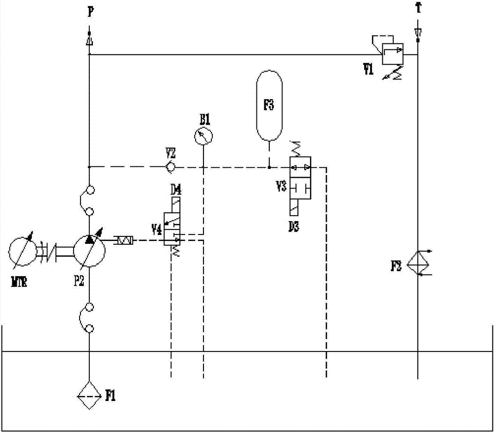
[0014] The present invention is a servo drive belt variable pump low speed control hydraulic circuit, such as figure 2 As shown, it includes system oil inlet P, oil suction filter F1, servo motor MTR, system oil outlet T, oil return filter F2, variable plunger pump P2, oil pump swing angle control valve V4, pressure relief valve V3, accumulator F3, pressure gauge B1 and control oil return check valve V2, circuit oil filter F2 is connected with system oil outlet T and system safety valve V1, system oil inlet P is connected with system safety valve V1, variable The plunger pump P2 is connected with the control oil return check valve V2, the variable plunger pump P2 is connected with the servo motor MTR, the oil suction filter F1 and the oil pump swing angle control valve V4, the control oil return check valve V2 is connected with the pressure gauge B1, ...


PUM


Abstract

The invention discloses a servo drive belt variable pump low-speed control hydraulic circuit. A circuit oil filter F2 is connected with a system oil outlet T and a system safety valve V1, a system oil inlet P is connected with the system safety valve V1, a variable plunger pump P2 and a control oil return-prevention one-way valve V2, the variable plunger pump P2 is connected with a servo motor MTR, an oil absorption oil filter F1 and an oil pump oscillating angle control valve V4, and the control oil return-prevention one-way valve V2 is connected with a pressure gage B1, the oil pump oscillating angle control valve V4, an energy accumulator F3 and a pressure release valve V3. The oil pump displacement is variable and adjustable, and the magnitude of the oscillating angle of an oil pump can be adjusted according to different requirements so that different working condition requirements, particularly occasions with a low speed requirement can be met; and the displacement output is reduced through reduction of the oscillating angle of the oil pump, the flow requirement of a system is met in the manner of increasing the rotation speed, rotation speed setting of servo power is based on the limiting value of the rotation speed, and the two parameters are matched within the stably-controlled range.

Description

technical field [0001] The invention relates to a hydraulic circuit, in particular to a low-speed control hydraulic circuit with a servo-driven variable pump. Background technique [0002] Modern injection molding machines commonly use hydraulic circuits with servo power and gear pump (quantitative) mode, such as figure 1 As shown, the oil inlet P of the system, the quantitative gear pump P1 and the oil suction filter F1 are connected in sequence, the quantitative gear pump P1 is connected with the servo motor MTR, and the circuit oil filter F2 is connected with the oil outlet T of the system and the safety valve V1 of the system. The system safety valve V1 is connected with the system oil inlet P and the quantitative gear pump P1. It is characterized by simplicity and reliability, and can meet most production needs. However, it has its shortcomings for the special needs of special industries. For occasions that require low-speed performance and high performance, because th...

Claims


Application Information

Patent Timeline
Patent Type & Authority Applications(China)
IPC IPC(8): F15B1/02F15B11/08F15B13/04F15B21/04
CPCF15B1/024F15B11/08F15B13/04F15B21/041F15B2211/20515F15B2211/20546F15B2211/212F15B2211/615
Inventor 张旭峰龚滨王李日生储进静
Owner WUXI HAITIAN MACHINERY
Why Eureka
Try Eureka