

Automatic control compressed air drainage device
A compressed air and water-repelling technology, applied in steam traps, mechanical equipment, etc., can solve problems such as inability to perform automatic water-repelling control, failure of floats, and high requirements for media
- Summary
- Abstract
- Description
- Claims
- Application Information
AI Technical Summary
Problems solved by technology
Method used
Image

Examples
Embodiment 1
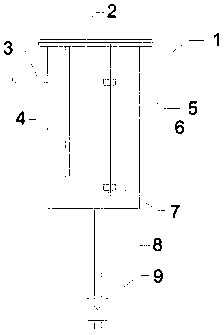
[0026] Embodiment 1: as figure 1 , 2 , shown in 6, an automatic control compressed air drainage device, comprising:
[0027] The tank body 1 connected with the compressed air outlet, the upper part of the tank body 1 is provided with an air inlet, and the air inlet is connected with an air inlet pipe 3 suitable for its diameter, so as to realize the connection with the compressed air outlet, so The top of the tank body 1 is open, the circumference is provided with a flange, the bottom of the tank body 1 is provided with a drain port, and the inside of the tank body 1 is provided with a baffle plate 4, which separates the tank body 1 into left and right parts. The upper part of the baffle 4 is opened to connect the left and right sides of the baffle 4 to exhaust gas. There is a gap between the bottom of the baffle 4 and the bottom of the tank body 1. The gap is 20 mm. The left and right sides of the baffle 4 are connected to form a U-shaped pipe to allow condensed water to pas...
Embodiment 2
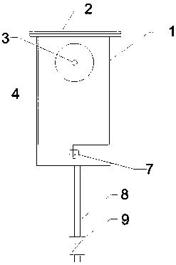
[0033] Embodiment 2: as image 3 , 4 , shown in 6, an automatic control compressed air drainage device, comprising:
[0034]The tank body 1 connected with the compressed air outlet, the upper part of the tank body 1 is provided with an air inlet, and the air inlet is connected with an air inlet pipe 3 suitable for its diameter, so as to realize the connection with the compressed air outlet, so The top of the tank body 1 is open, the circumference is provided with a flange, the bottom of the tank body 1 is provided with a drain port, and the inside of the tank body 1 is provided with a baffle plate 4, which separates the tank body 1 into left and right parts. The upper part of the baffle 4 is opened to connect the left and right sides of the baffle 4 to exhaust gas. There is a gap between the bottom of the baffle 4 and the bottom of the tank body 1. The gap is 20 mm. The left and right sides of the baffle 4 are connected to form a U-shaped pipe to allow condensed water to pass...
Embodiment 3
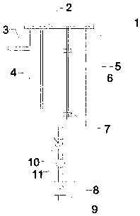
[0040] Embodiment 3: as figure 1 , 5 , shown in 6, an automatic control compressed air drainage device, comprising:
[0041] The tank body 1 connected with the compressed air outlet, the upper part of the tank body 1 is provided with an air inlet, and the air inlet is connected with an air inlet pipe 3 suitable for its diameter, so as to realize the connection with the compressed air outlet, so The top of the tank body 1 is open, the circumference is provided with a flange, the bottom of the tank body 1 is provided with a drain port, and the inside of the tank body 1 is provided with a baffle plate 4, which separates the tank body 1 into left and right parts. 4 The upper part is opened to connect the left and right sides of the baffle 4 to exhaust gas, and the lower part is provided with a filter hole 12. The left and right sides of the baffle 4 are connected to form a U-shaped pipe to allow condensed water to pass through and ensure that the water levels on both sides are co...
PUM
 Abstract
Description
Claims
Application Information