
Motor automatic oiling equipment

A kind of oiling equipment and fully automatic technology, which is applied in the direction of mechanical equipment, electric components, manufacturing motor generators, etc., can solve the problem of low oiling efficiency of bearings, and achieve the effect of improving work efficiency and sufficient oiling

Active Publication Date: 2020-09-15
中擎电机有限公司
View PDF8 Cites 0 Cited by
  • Summary
  • Abstract
  • Description
  • Claims
  • Application Information

AI Technical Summary

Problems solved by technology

[0003] The motor automatic oiling equipment proposed by the present invention solves the problem of low bearing oiling efficiency in the existing motor production process

Method used


Image

  • Motor automatic oiling equipment
  • Motor automatic oiling equipment
  • Motor automatic oiling equipment

Examples


Embodiment Construction

[0023] The following will clearly and completely describe the technical solutions in the embodiments of the present invention with reference to the accompanying drawings in the embodiments of the present invention. Obviously, the described embodiments are only some, not all, embodiments of the present invention.

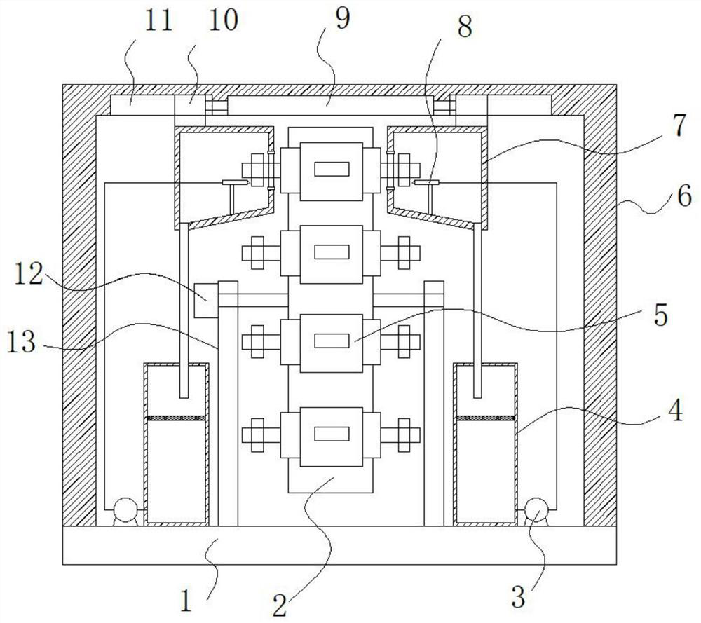
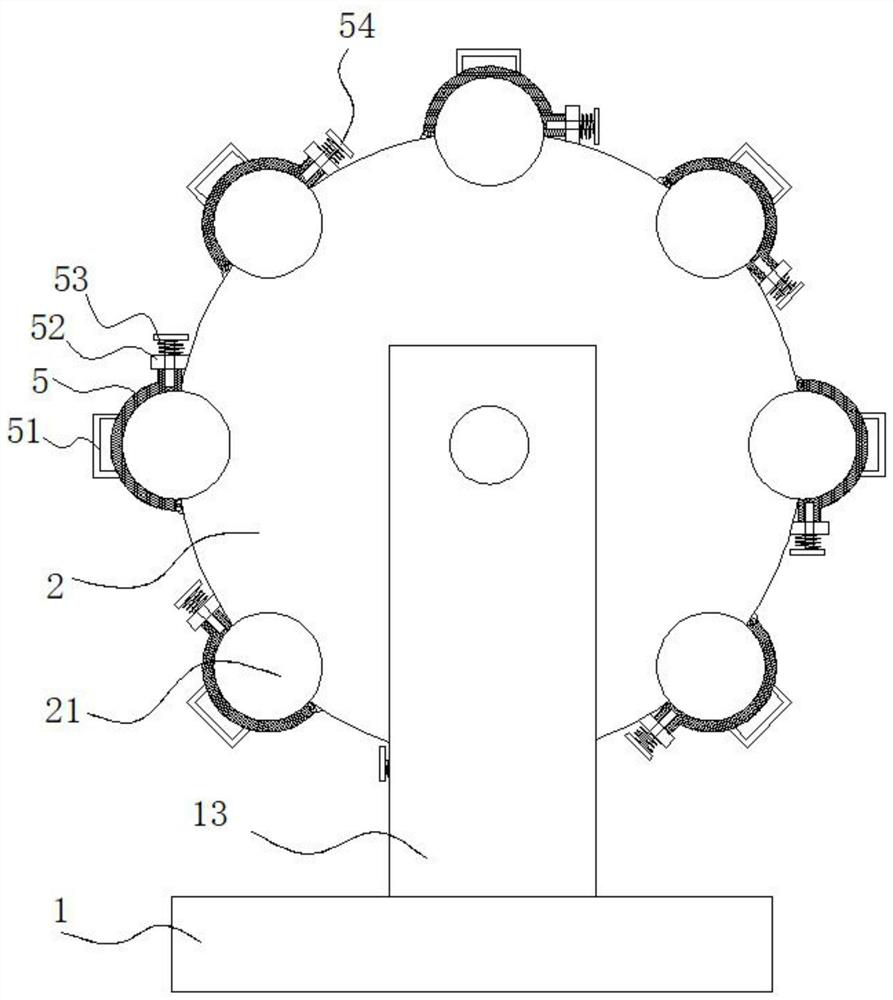
[0024] refer to Figure 1-3 , motor automatic oiling equipment, including a base 1, a support frame 13 is installed in the middle of the top of the base 1, a motor 2 12 is installed on the side wall of the support frame 13, and the output shaft of the motor 2 12 is connected with a rotating connection on the support The rotating disk 2 inside the frame 13 has a plurality of fixing grooves 21 arranged in an annular array on the outer wall of the rotating disk 2, and the fixing groove 21 is provided with a locking mechanism;

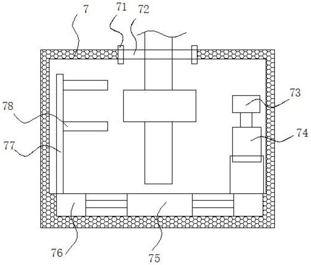
[0025] The top of the base 1 is equipped with a fixed frame 6 positioned at the outside of the rotating disk 2, and a double-headed cylinder-9 t...


PUM


Abstract

The invention belongs to the field of motor bearings, and especially provides full automatic oil injection equipment for a motor. The following scheme is put forward. The full automatic oil injectionequipment comprises a base. A support frame is arranged at the middle position of the top end of the base. A motor 2 is installed on the side wall of the support frame. The output shaft of the motor 2is connected with a rotating disc rotatably connected inside the support frame. A plurality of annular-array-arranged fixing grooves are arranged on the outer side wall of the rotating disc, and a locking mechanism is arranged on the fixing grooves. The top end of the base is provided with a fixing frame located outside the rotating disc. A horizontal double-head cylinder 1 is arranged on the topinner wall of the fixing frame. The two output shafts of the double-head cylinder 1 are connected with a slide block 1. Working boxes located on the two sides of the rotating disc are arranged on thebottom end of the slide block 1. A communication hole is arranged in the side wall of the working boxes close to the rotating disc. The device can quickly realize oil injection of the bearing of themotor rotor and has good oil injection effect and high working efficiency.

Description

technical field [0001] The invention relates to the technical field of motor bearing oil injection, in particular to automatic motor oil injection equipment. Background technique [0002] The motor mainly relies on the relative rotation of its stator and rotor to output torque. The motor stator is fixed on the motor frame, while the rotor and its rotor shaft are supported on the motor frame through bearings and motor end covers. Therefore, the bearing is an important load-bearing element when the motor is working. During the production process of the motor, the bearings at both ends of the rotor shaft need to be filled with oil, and then installed. Most of the bearings on the existing motor rotor are oiled manually by the staff. The work efficiency is low, and the oil injection is uneven, so we propose a motor automatic oil injection equipment. Contents of the invention [0003] The motor automatic oiling equipment proposed by the invention solves the problem of low beari...

Claims


Application Information

Patent Timeline
Patent Type & Authority Patents(China)
IPC IPC(8): H02K15/00H02K15/14F16N39/06F16N7/30
CPCF16N7/30F16N39/06H02K15/00H02K15/14
Inventor 林波叶灵荣林娜金新兵叶云兰
Owner 中擎电机有限公司
Learn More