Electronic control valve assembling method and system

A technology of electronically controlled valves and assembly methods, which is applied in the direction of assembly machines, metal processing equipment, manufacturing tools, etc., can solve problems such as increased noise of electronically controlled valve assemblies, sticking of moving iron cores, and changes in movable gaps, etc., to achieve reduction noise effect

Active Publication Date: 2019-12-06
佛山市南海科惠汽配有限公司
View PDF8 Cites 1 Cited by
  • Summary
  • Abstract
  • Description
  • Claims
  • Application Information

AI Technical Summary

Problems solved by technology

In the process of assembling the bellows and the third component, the coil plane is used to position the bellows on the third component. However, after the assembly of the electric control valve is completed, due to the insufficient flatness of the coil plane There is an eccentric phenomenon of the force on the iron core. During the performance test of the electric control valve, the movable gap between the moving iron core and the magnetic isolation sleeve changes, and the moving iron core is stuck.
And when the vibration frequency of the electric control valve was tested at 400HZ for 1 second, it was found that the vibration of the moving iron core was too large, and the noise of the electric control valve assembly became louder.

Method used


Image

  • Electronic control valve assembling method and system
  • Electronic control valve assembling method and system

Examples


Embodiment Construction

[0021] Embodiments of the present application are described in detail below, examples of which are shown in the drawings, wherein the same or similar reference numerals denote the same or similar elements or elements having the same or similar functions throughout. The embodiments described below by referring to the figures are exemplary only for explaining the present application, and are not construed as limiting the present application.

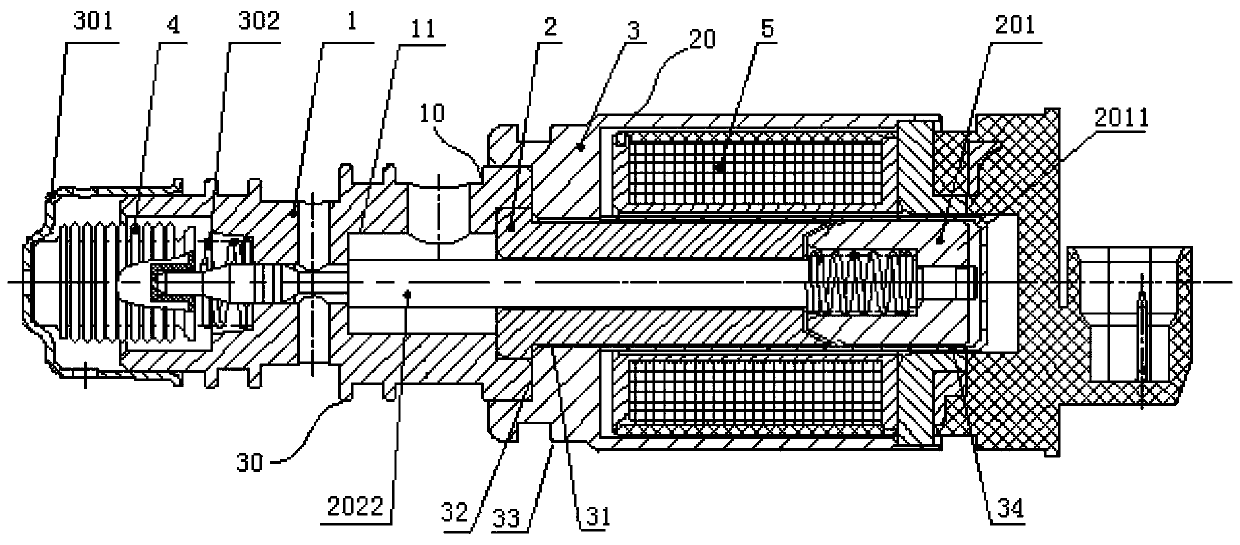
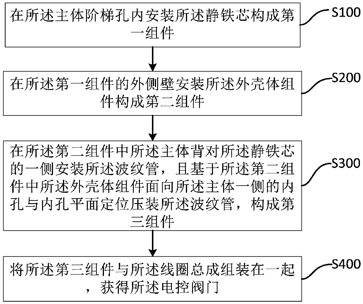
[0022] This application provides a method for assembling an electronically controlled valve, such as figure 1 As shown, the electronically controlled valve includes: a main body 1, a static iron core 2, an outer casing assembly 3, a bellows 4, and a coil assembly 5, wherein, as figure 2 As shown, the steps of the electronic control valve assembly method include: S100, S200, S300, S400, S310:

[0023] S100: Install the static iron core 2 in the stepped hole 11 of the main body 1 to form a first assembly 10;

[0024] S200: Install the out...


PUM


Abstract

The invention discloses an electronic control valve assembling method. An electronic control valve comprises a body, a static iron core, an outer shell assembly, a corrugated pipe and a coil assembly.The assembling method is characterized by comprising the steps that the static iron core is mounted in a stepped hole of the body, so that a first assembly is formed; the outer shell assembly is mounted on the outer side wall of the first assembly, so that a second assembly is formed; the corrugated pipe is mounted on the side, back onto the static iron core, of the body in the second assembly, and the corrugated pipe is positioned and press fitted based on an inner hole and an inner hole plane in the side, facing the body, of the outer shell assembly in the second assembly, so that a third assembly is formed; and the third assembly and the coil assembly are assembled together to obtain the electronic control valve. The corrugated pipe is positioned and press fitted by adopting the outershell assembly inner hole and the inner hole plane, stress directions of a movable iron core during moving are effectively guaranteed to be concentric, and therefore, it is guaranteed that noise of the whole electronic control valve during using is lowered while the frequency per second of the electronic control valve is 400 HZ.

Description

technical field [0001] The present application relates to the technical field of electronics and electronic assembly, and in particular, the present application relates to an electronic control valve assembly method and system. Background technique [0002] The main assembly process in the assembly process of the existing electric control valve is divided into four steps; step 1: assembling the main body and the conduit to form the first assembly, step 2: assembling the first assembly and the outer shell assembly to form the second assembly, Step 3: Assemble the coil assembly with the second component to form the third component. Step 4: Assemble the bellows with the third component. In the process of assembling the bellows and the third component, the coil plane is used to position the bellows on the third component. However, after the electric control valve is assembled, due to the insufficient flatness of the coil plane, the dynamics in the electric control valve There i...

Claims


Application Information

Patent Timeline
Patent Type & Authority Applications(China)
IPC IPC(8): B23P21/00
CPCB23P21/002
Inventor 习沧海
Owner 佛山市南海科惠汽配有限公司
Why Eureka
Try Eureka