Backfill sampling device for project supervision
A technology of sampling device and backfilling soil, which is applied in the direction of sampling device, etc., can solve the problems such as easy drop of soil samples, closed protection of soil samples that cannot be taken out, and influence on sampling stability, so as to achieve increased stability, good material guiding effect, The effect of simple structure
- Summary
- Abstract
- Description
- Claims
- Application Information
AI Technical Summary
Problems solved by technology
Method used
Image

Examples
Embodiment
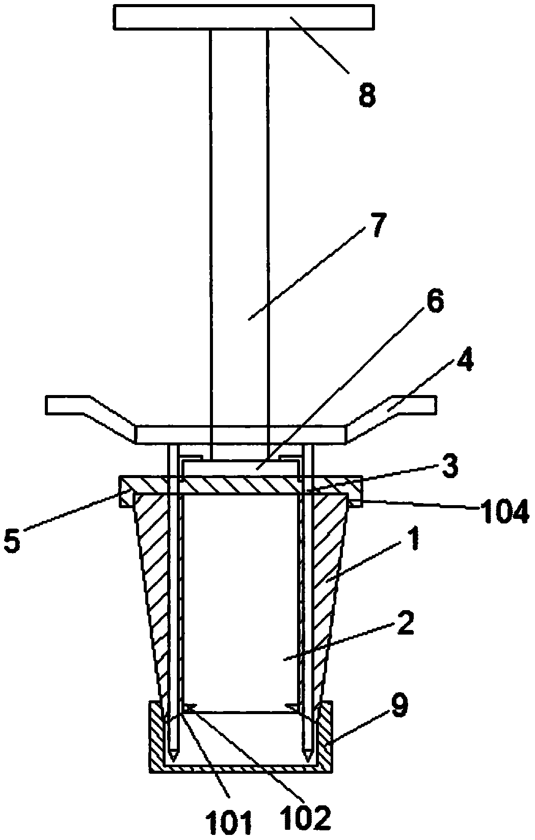
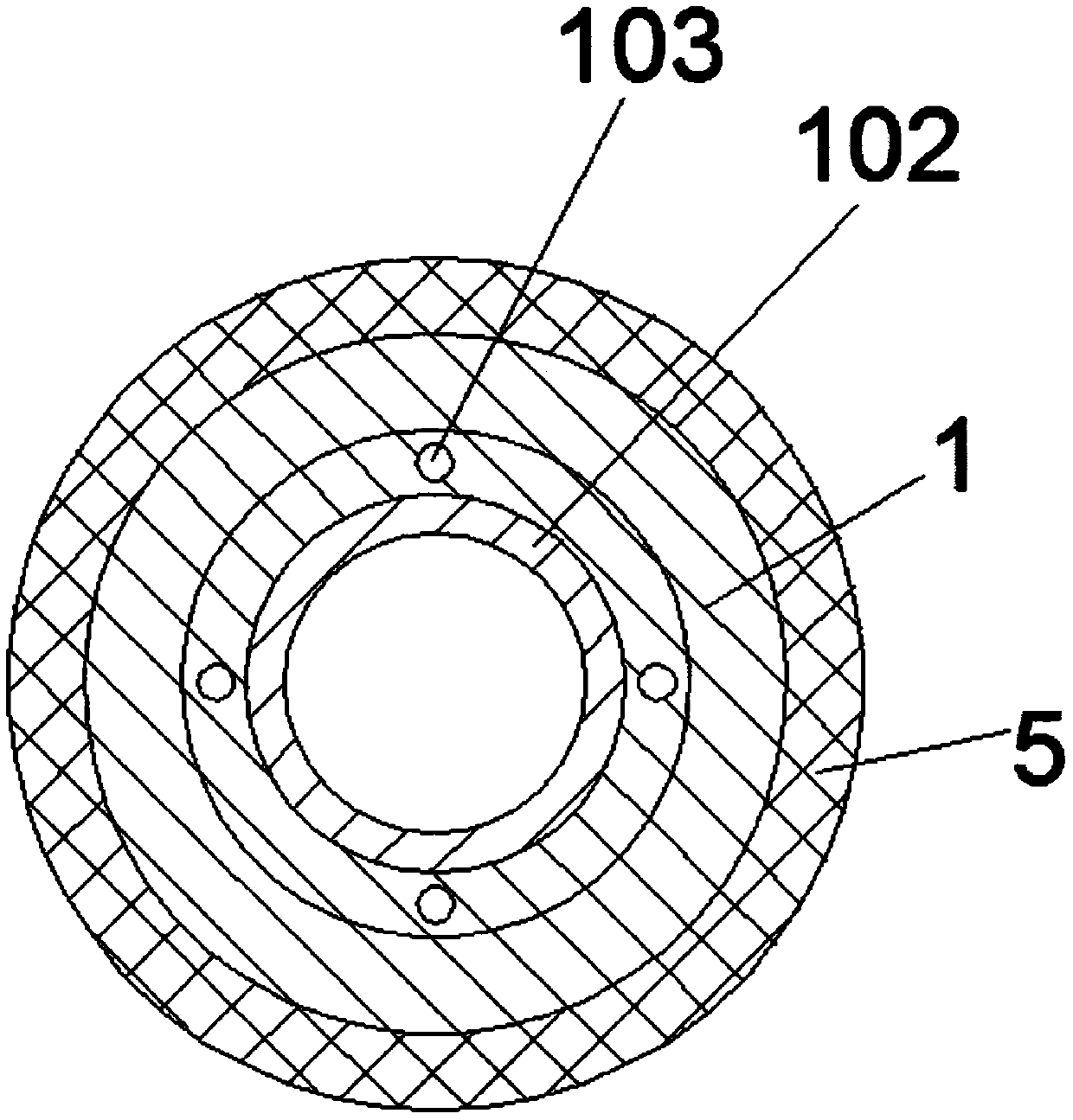
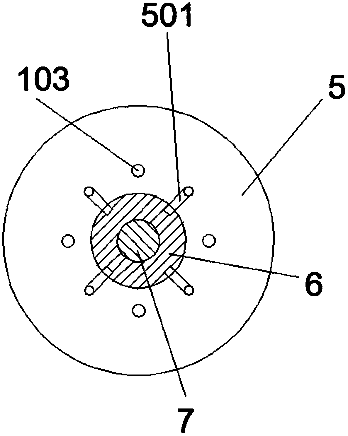
[0023] Such as Figure 1-5 as shown,
[0024] This embodiment provides a backfill soil sampling device for engineering supervision, comprising a sampling housing 1 with a conical structure on the outside. The inside of the sampling housing 1 is a cylindrical sampling cavity 2. A number of guiding and fixing columns 3 are evenly distributed, and the upper part of the guiding and fixing columns 3 is provided with a pressing plate 4. The upper part of the sampling housing 1 is threaded with a thrust cover 5, and the thrust cover 5 is movably connected with a push block 6. A threaded push rod 7 is formed on the push block 6, and the threaded push rod 7 is threadedly connected with the pressing plate 4. The end of the threaded push rod 7 is provided with an annular handle 8, and the end of the sampling housing 1 is provided with a Corresponding to the material guide port 101 of the cylindrical sampling cavity 2 , the inside of the sampling housing 1 is provided with an anti-backfl...
PUM
 Abstract
Description
Claims
Application Information
PatSnap Eureka turns technology decisions into work you can execute. Powered by our Innovation Knowledge Graph, it runs expert workflows across engineering, life sciences, materials and intellectual property. Get your review-ready output in minutes.


