Supercharge Your Innovation With Domain-Expert AI Agents!

A method for realizing gate control isolation and a gate control circuit

A grid control and grid control technology, which is applied to electrical components, X-ray equipment, etc., can solve the problems of strong interference of grid control circuits and high safety isolation requirements of grid control circuits, and achieve the effect of solving security isolation problems.

Active Publication Date: 2021-01-08
NANOVISION TECHNOLOGY (BEIJING) CO LTD
View PDF14 Cites 0 Cited by
  • Summary
  • Abstract
  • Description
  • Claims
  • Application Information

AI Technical Summary

Problems solved by technology

Moreover, the gate control terminal of the X-ray tube generally works at a very high voltage (thousands of volts to tens of kilovolts), which requires high safety isolation for the gate control circuit, and also needs to solve the The problem of strong interference from sparking to the gate-level control circuit

Method used


Image

  • A method for realizing gate control isolation and a gate control circuit
  • A method for realizing gate control isolation and a gate control circuit
  • A method for realizing gate control isolation and a gate control circuit

Examples


Embodiment Construction

[0035] The technical content of the present invention will be further described in detail below in conjunction with the accompanying drawings and specific embodiments.

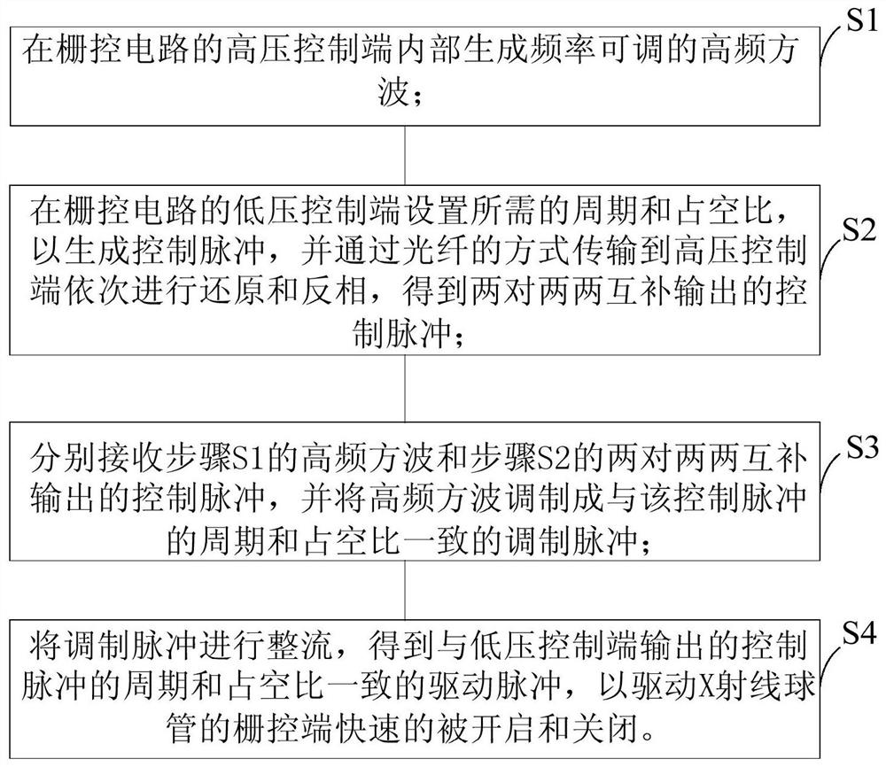
[0036] It should be noted that the gate-control isolation method provided in the present invention refers to a method for implementing safe isolation of the gate-level control circuit of the X-ray tube. Such as figure 1 As shown, the method includes the following steps:

[0037] Step S1: generating a high-frequency square wave with adjustable frequency inside the high-voltage control terminal of the gate control circuit;

[0038] By setting an oscillation unit in the gate control circuit, a high-frequency square wave with a preset duty cycle and adjustable frequency can be generated inside the high-voltage control terminal of the gate control circuit. The duty cycle and frequency of the high-frequency square wave can be adjusted by the oscillation unit according to the duty cycle and frequency required for d...


PUM


Abstract

The invention discloses a method for realizing grid control isolation and a grid control circuit. The method comprises the following steps: firstly, generating a frequency-adjustable high-frequency square wave in a high-voltage control end of a gate control circuit; setting a required period and a duty ratio at a low-voltage control end of the gate control circuit to generate a control pulse, andtransmitting the control pulse to a high-voltage control end in an optical fiber mode to perform reduction and phase inversion in sequence to obtain two pairs of control pulses which are complementarily output in pairs; respectively receiving a high-frequency square wave and two pairs of control pulses which are complementarily output in pairs, and modulating the high-frequency square wave into amodulation pulse which is consistent with the control pulse in period and duty ratio; and isolating and rectifying the modulation pulse to obtain a driving pulse consistent with the period and the duty ratio of the control pulse so as to drive the grid control end of an X-ray bulb tube to be quickly opened and closed. According to the invention, the pulse width and the duty ratio can be adjusted at will. And the safety isolation problem caused by controlling the grid control end of the X-ray bulb tube during high-voltage on-off is also solved.

Description

technical field [0001] The invention relates to a method for realizing gate control isolation, and also relates to a gate control circuit adopting the method. Background technique [0002] Currently, all kinds of medical X-ray equipment on the market have high-voltage generators and X-ray tubes. The high-voltage generator is used to generate kilovolt-level DC high voltage, which can be positive high voltage or negative high voltage. DC high voltage is loaded between the cathode and anode of the X-ray tube, so that the filament in the X-ray tube is heated to generate electrons, and then bombards the anode target surface under the acceleration of the high-voltage electric field to generate X-rays. In practical applications, it is necessary to control the "presence" and "absence" of the X-rays of the X-ray tube according to a certain time sequence to achieve a certain application purpose. [0003] In the prior art, the X-ray tube is generally equipped with a grid control swit...

Claims


Application Information

Patent Timeline
Patent Type & Authority Patents(China)
IPC IPC(8): H05G1/08
CPCH05G1/085
Inventor 崔亮崔志立
Owner NANOVISION TECHNOLOGY (BEIJING) CO LTD
Features
  • R&D
  • Intellectual Property
  • Life Sciences
  • Materials
  • Tech Scout
  • Unparalleled Data Quality
  • Higher Quality Content
  • 60% Fewer Hallucinations
Learn More