Supercharge Your Innovation With Domain-Expert AI Agents!

A multi-channel communication method between a power cable detection device and an acquisition device

A technology of a detection device and a collection device, applied in the field of data communication, can solve the problems of easy shielding of signals, difficulty in laying, and increase in cost, and achieve the effects of solving the problem of safety isolation, overcoming poor signals, and solving high power consumption

Active Publication Date: 2015-11-04
BEIJING HAORUIDA TECH
View PDF3 Cites 0 Cited by
  • Summary
  • Abstract
  • Description
  • Claims
  • Application Information

AI Technical Summary

Problems solved by technology

Among them, the wireless method is easily affected by the on-site environment, such as on-site signal interference, communication signals are easily shielded, etc., and the detection device using the wireless method is generally powered by batteries. Due to its high power consumption, the cost must be increased for Power consumption design, its application effect is not ideal
One of the wired communication methods is to use cable transmission. This method cannot isolate the primary equipment and the secondary equipment very well. It is easy to introduce the high voltage of the primary side to the secondary side at the installation point with poor insulation; Communication optical fiber is used for transmission, but its cost is high, it is not easy to lay, the maintenance is complicated, and the flexibility is not good, and this wired method can only use point-to-point communication, and one acquisition device can only collect data from one detection device , its scalability is not strong, and it cannot meet the application of multi-switch monitoring control

Method used


Image

  • A multi-channel communication method between a power cable detection device and an acquisition device
  • A multi-channel communication method between a power cable detection device and an acquisition device
  • A multi-channel communication method between a power cable detection device and an acquisition device

Examples


Embodiment Construction

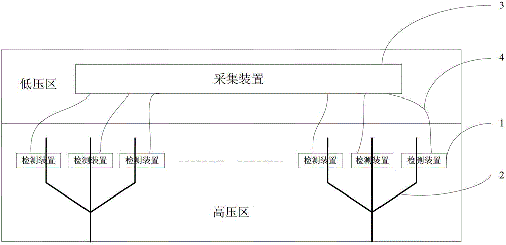
[0021] Such as figure 1 As shown, the detection device 1 of the present invention is installed on the power cable 2 of the high-voltage primary side, and the collection device 3 is installed on the low-voltage secondary side; the output pin of the CPU of the detection device is connected to the luminescent tube, and the IO pin of the CPU of the collection device The feet are connected to the photosensitive tube, and the luminescent tube is connected to the photosensitive tube through an optical fiber 4 . One collection device of the present invention can be connected with multiple detection devices by optical fibers at the same time, so that one collection device can perform data communication with multiple detection devices at the same time. The communication distance can reach 15 meters.

[0022] The above-mentioned optical fiber of the present invention can be a plastic plastic optical fiber. The cost of plastic optical fiber is low, and it can well isolate primary equipm...


PUM


Abstract

Disclosed is a method of multi-channel communication between an electrical cable detecting device and an acquiring device. The detecting device is mounted on a high-voltage primary side of an electrical cable, and the acquiring device is mounted on the low-voltage secondary side. A CPU (central processing unit) output pin of the detecting device is connected with a light emitting tube, a CPU IO (input output) pin of the acquiring device is connected with a photosensitive tube, and the light emitting tube and the photosensitive tube are connected through an optical fiber. The detecting device acquires current, voltage and temperature information in the electrical cable and controls on and off of the light emitting tube through a CPU, and the acquired current, voltage and temperature information can be transmitted to the optical fiber via optical signals by means of Manchester encoding to generate a light emitting and non-emitting transmission sequence. The acquiring device receives 'light emitting' or 'non-emitting' optical signals transmitted by the detecting device through the optical fiber by the aid of the photosensitive tube and converts the optical signals into electrical signals with high and low level to input into the CPU IO pin, and data decoding is completed by the CPU.

Description

technical field [0001] The invention relates to data communication between a power cable detection device and a collection device in the electric power industry, and is especially applied to multi-channel concurrent serial communication. Background technique [0002] Power cables play an important role in the construction of distribution network, and their monitoring is directly related to the reliability and quality of power supply. The cable line monitoring device includes a line information detection device and a data acquisition device. The detection device is in direct contact with the cable to detect analog signal quantities such as current and voltage in the cable, and then the detection device CPU passes the monitoring information through wired or wireless data according to digital coding The communication is transmitted to the collection device, and the CPU of the collection device obtains information such as current and voltage in the cable through decoding. Gener...

Claims


Application Information

Patent Timeline
Patent Type & Authority Patents(China)
IPC IPC(8): H04B10/25
Inventor 薛兆春
Owner BEIJING HAORUIDA TECH
Features
  • R&D
  • Intellectual Property
  • Life Sciences
  • Materials
  • Tech Scout
  • Unparalleled Data Quality
  • Higher Quality Content
  • 60% Fewer Hallucinations
Learn More