

Clamping workbench for electric push rod machining
An electric push rod and worktable technology, applied in worktables, workpiece clamping devices, lighting devices, etc., can solve the problems of non-adjustable height and slow clamping speed, so as to solve the problem of slow clamping speed and fast clamping speed. Effect
- Summary
- Abstract
- Description
- Claims
- Application Information
AI Technical Summary
Problems solved by technology
Method used
Image

Examples
Embodiment 1
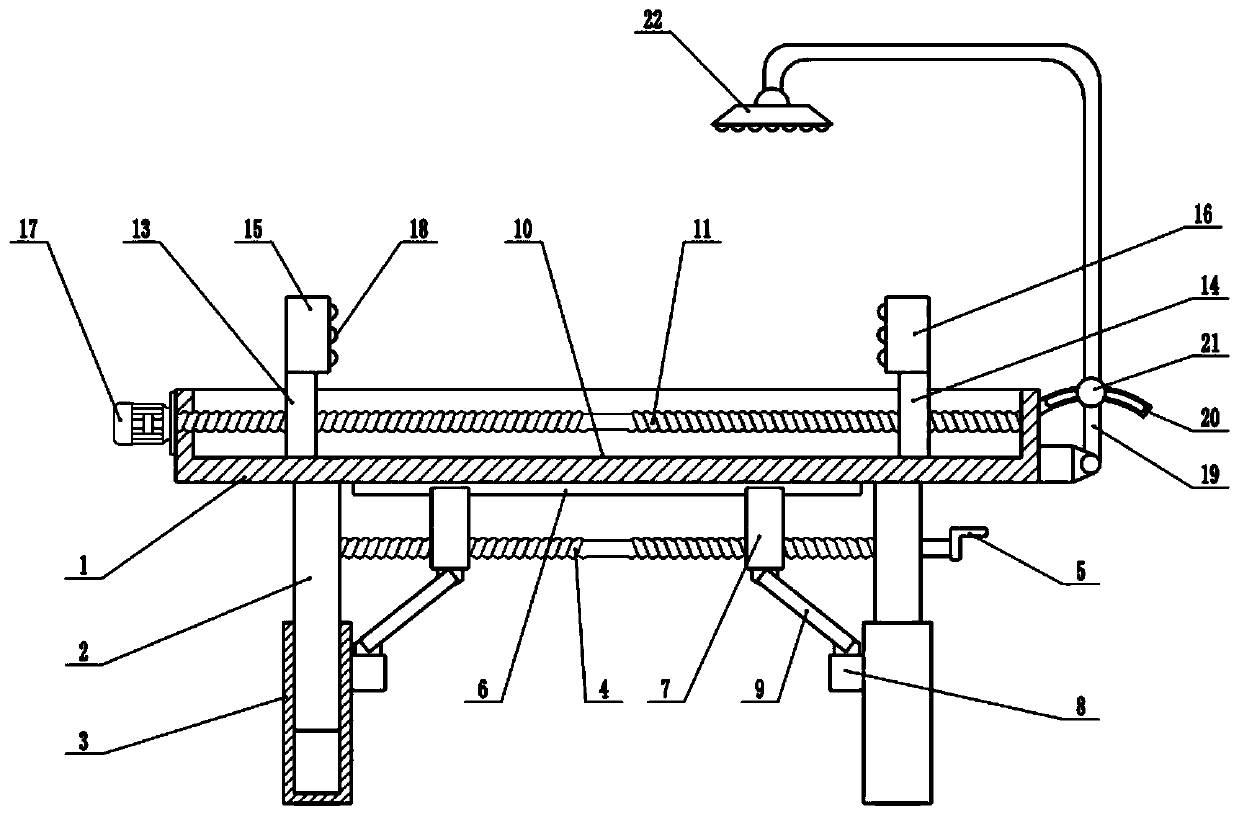
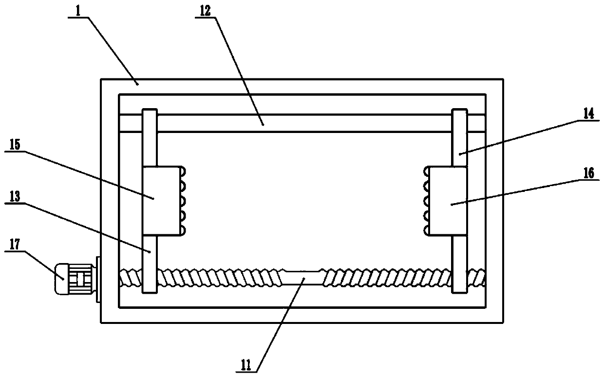
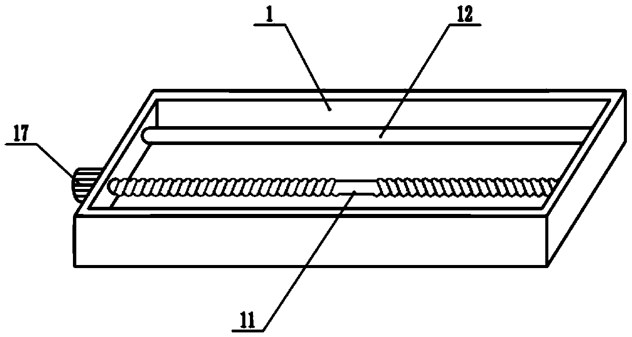
[0020] see Figure 1-3 , in an embodiment of the present invention, a clamping workbench for electric push rod processing includes a frame 1, a movable plate 2, a left movable plate 13, a right movable plate 14, a left clamping block 15 and a right clamping block 16. The lower surface of the frame 1 is fixedly connected with a movable plate 2. There are two movable plates 2, which are arranged symmetrically. , the two ends of the second two-way screw mandrel 11 are respectively connected with the side wall of the chute 10 in rotation, the two ends of the second two-way screw mandrel 11 are respectively sleeved with a left movable plate 13, a right movable plate 14, a left movable plate 13, a right movable plate Movable plate 14 is threadedly connected with second two-way screw mandrel 11 respectively, and the top of left movable plate 13 is equipped with left clamping block 15, and the top of right movable plate 14 is equipped with right clamping block 16, and the inside of ch...
Embodiment 2
[0022] On the basis of Embodiment 1, a height adjustment mechanism is installed below the frame 1, and the height adjustment mechanism includes a fixed plate 3, a first two-way screw rod 4, a slide rail 6, a slider 7, a fixed block 8 and a connecting rod 9, The lower end of the movable plate 2 is covered with a fixed plate 3, and the top of the fixed plate 3 is provided with a sliding cavity, the movable plate 2 extends into the sliding cavity, the movable plate 2 is slidably connected with the fixed plate 3, and the movable plate 2 can go up and down along the sliding cavity Sliding, the bottom of the frame 1 is provided with the first two-way screw rod 4, the end of the first two-way screw rod 4 is connected with the movable plate 2 in rotation, the right end of the first two-way screw rod 4 is equipped with a rocker 5, the first two-way screw rod 4 The rod 4 is provided with a slide block 7, and there are two slide blocks 7, which are arranged symmetrically. The slide block ...
Embodiment 1、 Embodiment 2
[0023] In conjunction with Embodiment 1 and Embodiment 2, the working principle of the present invention is: place the electric push rod part to be processed between the left clamping block 15 and the right clamping block 16, start the clamping motor 17, and drive the second two-way The screw mandrel 11 rotates to drive the left clamping block 15 and the right clamping block 16 to move towards each other, and the left clamping block 15 and the right clamping block 16 are used to clamp the workpiece to be processed. After clamping, the self-locking effect of the screw rod is used to make the The left clamping block 15 and the right clamping block 16 remain stable, and the clamping speed is fast, which is very convenient. When it is necessary to adjust the lighting angle, unscrew the positioning bolt 21, so that the support rod 19 can swing freely, and adjust the angle of the support rod 19. In order to adjust the lighting angle, when the height of the rack 1 needs to be adjusted...
PUM
 Abstract
Description
Claims
Application Information