Stopper and test tube assembly
A test tube and plug technology, which is applied in the directions of using plugs to seal, seal plugs, and closures, can solve the problems of many steps and easy to find plugs, and achieve the effect of good airtightness, fast and convenient force, and not easy to leak.
- Summary
- Abstract
- Description
- Claims
- Application Information
AI Technical Summary
Problems solved by technology
Method used
Image


Examples
Embodiment 1
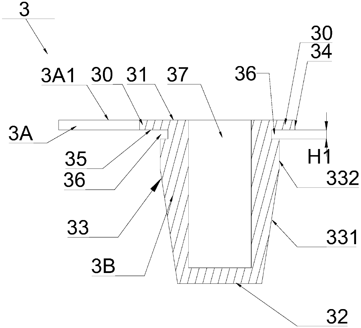
[0077] Embodiment 1: the following combination figure 1 , figure 2 The present invention is described further:
[0078] A plug 3 includes a hanging portion 3A and a sealing portion 3B. The hanging portion 3A is integrated with the sealing portion 3B.
[0079] The sealing portion 3B includes an upper end surface 31 , a lower end surface 32 , an outer surface 33 and a flange 30 . The flange 30 is annular and formed by extending outward from the upper outer surface 33 of the sealing portion 3B. Wherein, the upper end surface 31 and the flange bottom surface 35 are connected by the flange side surface 34 , and the flange bottom surface 35 and the lower end surface 32 are connected by the outer surface 33 . Different slopes are provided on the outer surface 33 , and the outer surface 33 includes a cylindrical portion 332 and a tapered portion 331 . An annular groove 36 is formed at the junction of the flange bottom surface 35 and the outer surface 33 . A blind hole 37 opened...
Embodiment 2
[0081] Embodiment 2: combine below Figure 1 to Figure 7 The present invention is described further:
[0082] A test tube assembly, including a stopper 3 and a test tube 1.
[0083] The plug 3 includes a hanging portion 3A and a sealing portion 3B. The hanging portion 3A is integrated with the sealing portion 3B.
[0084] The sealing portion 3B includes an upper end surface 31 , a lower end surface 32 , an outer surface 33 and a flange 30 . The flange 30 is annular and formed by extending outward from the upper outer surface 33 of the sealing portion 3B. Wherein, the upper end surface 31 and the flange bottom surface 35 are connected by the flange side surface 34 , and the flange bottom surface 35 and the lower end surface 32 are connected by the outer surface 33 . The outer diameter of the outer side 33 is smaller than the outer diameter of the flange side 34 . Different slopes are provided on the outer surface 33 , and the outer surface 33 includes a cylindrical portion...
Embodiment 3
[0093] Embodiment 3: combine below Figure 5 to Figure 13 The present invention is described further:
[0094] A test tube assembly, comprising a stopper 3, a built-in stopper 2 and a test tube 1.
[0095] The test tube 1 is provided with an opening 11 , and an inner wall 13 of the opening 11 is provided with an annular groove 12 .
[0096]The built-in plug 2 is provided with a channel 21 . Below the channel 21 there are four sealing membranes 22 which form a cross shape; A depression 23 is provided above the 4 pieces of sealing membrane 22 . An annular protrusion B 25 is provided on the inner wall 24 at the upper end of the channel 21 . An annular shoulder 27 is provided on the outer wall 26 of the built-in plug 2 .
[0097] The plug 3 includes a hanging portion 3A and a sealing portion 3B. The hanging portion 3A is integrated with the sealing portion 3B.
[0098] The sealing portion 3B includes an upper end surface 31 , a lower end surface 32 and a flange 30 . The fl...
PUM
 Abstract
Description
Claims
Application Information