Sectional chock-flow type pipeline self-sealing valve

A pipeline and choke technology, applied in the field of segmented choke pipeline self-sealing valves, can solve the problems of equipment and ground pollution, medium discharge, complicated installation methods, etc., to avoid a large amount of leakage and outflow, and to achieve the effect of convenience, speed and installation.

Active Publication Date: 2019-12-10
台州市路桥鸿辉水暖厂
View PDF10 Cites 3 Cited by
  • Summary
  • Abstract
  • Description
  • Claims
  • Application Information

AI Technical Summary

Problems solved by technology

[0006] The purpose of the present invention is to provide a segmented flow-blocking pipeline self-sealing valve to solve the current valve installation structure on the market proposed by the above-mentioned background technology. When disassembling the valve plate, the entire valve body needs to be disassembled before the valve When replacing the valve on the valve, when installing the valve body again, it is necessary to connect the flanges on both sides of the valve body with the two nozzles. The medium inside the pipes on both sides is discharged. If the medium is liquid, it is more likely to cause pollution to the equipment and the ground near the valve.

Method used


Image

  • Sectional chock-flow type pipeline self-sealing valve
  • Sectional chock-flow type pipeline self-sealing valve
  • Sectional chock-flow type pipeline self-sealing valve

Examples


Embodiment Construction

[0028] Based on the embodiments of the present invention, all other embodiments obtained by persons of ordinary skill in the art without making creative efforts belong to the protection scope of the present invention.

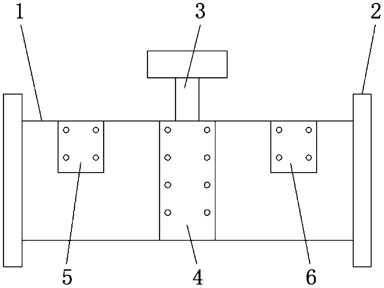
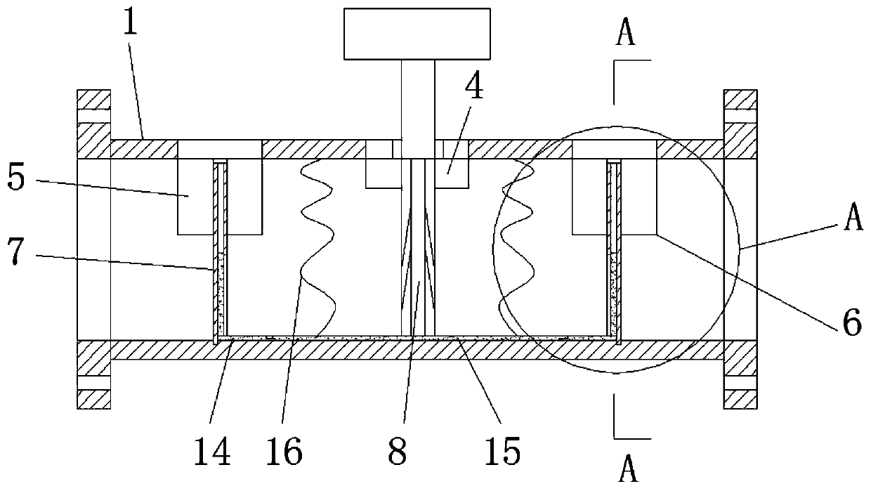
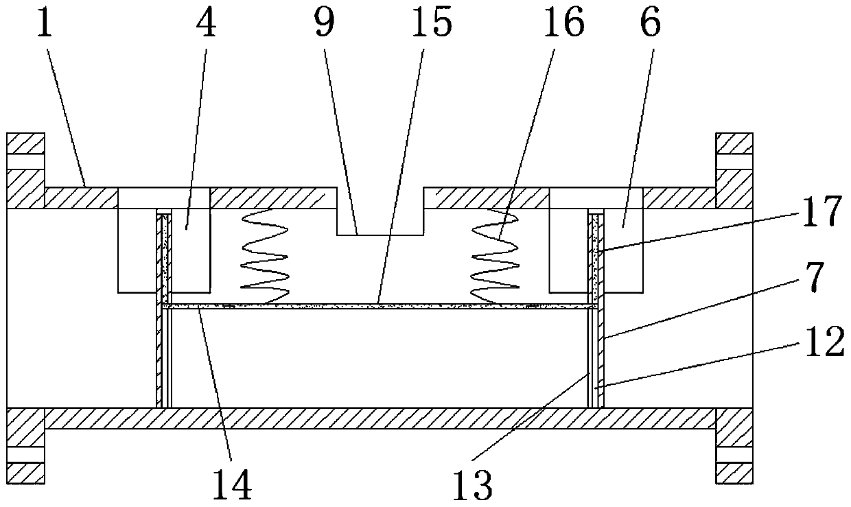
[0029] see Figure 1-9 , the present invention provides a technical solution: a segmented blocking type pipeline self-sealing valve, valve body 1, flange plate 2, valve stem 3, first sealing plate 4, second sealing plate 5, third sealing plate 6 , spoiler 7, valve plate 8, first installation port 9, second installation port 10, third installation port 11, sliding groove 12, sliding port 13, connecting rod 14, linkage rod 15, return spring 16, seal Plate 17, top sealing block 18, first sealing ring 19, second sealing ring 20, sealing groove 21, installation groove 22 and water outlet 23, flanges 2 are welded on both sides of valve main body 1, and valve main body 1 There is a first installation port 9 in the middle part of the center, and the second installatio...


PUM


Abstract

The invention discloses a sectional chock-flow type pipeline self-sealing valve. The sectional chock-flow type pipeline self-sealing valve comprises a valve main body, flange plates, a valve rod, a valve plate, first sealing rings and a second sealing ring, the flange plates are correspondingly welded to the two sides of the valve main body, a first mounting opening is formed in the middle of thevalve main body, a second mounting opening and a third mounting opening are formed in the two sides of the third mounting opening correspondingly, meanwhile the first mounting opening, the second mounting opening and the third mounting opening are correspondingly connected with a first sealing plate, a second sealing plate and a third sealing plate through bolts, connecting rods on the lower partsof the sealing plates are located at sliding openings in the lower parts of chock-flow plates, connecting rods on the two chock-flow plates are connected with linkage rods through screws, the first sealing rings are correspondingly arranged on the two sides of the sealing plates, and meanwhile upper part screws of the linkage rods are connected with reset springs. According to the sectional chock-flow type pipeline self-sealing valve, the valve in the valve body is blocked, and when the valve plate is dismantled, mediums in the pipelines on the two sides of the valve plate can be avoided fromflowing out

Description

technical field [0001] The invention relates to the technical field of valves, in particular to a section-block flow-type pipeline self-sealing valve. Background technique [0002] The valve is a control device in the pipeline for controlling the medium. The medium conveyed in the pipeline can be gas or liquid. The valve can control the circulation or cut-off of the medium in the pipeline. The control valves used in the pipeline can be divided into manual and automatic Control two kinds of valves, both of which can control the control of the circulating medium inside the conveying pipeline. Manual valves are mainly used in the control of water flow pipelines, while automatic valves are mainly used in the control of gaseous media. [0003] The existing valves are mainly fixed at the junction of two pipelines through the flanges at both ends to realize the control of the medium in the pipeline, but the following problems exist in the daily maintenance and replacement of the va...

Claims


Application Information

Patent Timeline
Patent Type & Authority Applications(China)
IPC IPC(8): F16K3/02F16K3/314F16K27/04F16K43/00
CPCF16K3/0209F16K3/029F16K3/314F16K27/044F16K43/006
Inventor 吴紫阳
Owner 台州市路桥鸿辉水暖厂
Why Eureka
Try Eureka