RF frequency synthesis based on offset optical frequency combs in ring resonators

A technology of ring resonators and optical frequency combs, applied in optics, optical demodulation, optical components, etc., can solve problems such as low efficiency

Active Publication Date: 2019-12-10
HONEYWELL INT INC
View PDF11 Cites 4 Cited by
  • Summary
  • Abstract
  • Description
  • Claims
  • Application Information

AI Technical Summary

Problems solved by technology

However, the process is less efficient because most of the s

Method used


Image

  • RF frequency synthesis based on offset optical frequency combs in ring resonators
  • RF frequency synthesis based on offset optical frequency combs in ring resonators
  • RF frequency synthesis based on offset optical frequency combs in ring resonators

Examples


Embodiment 1

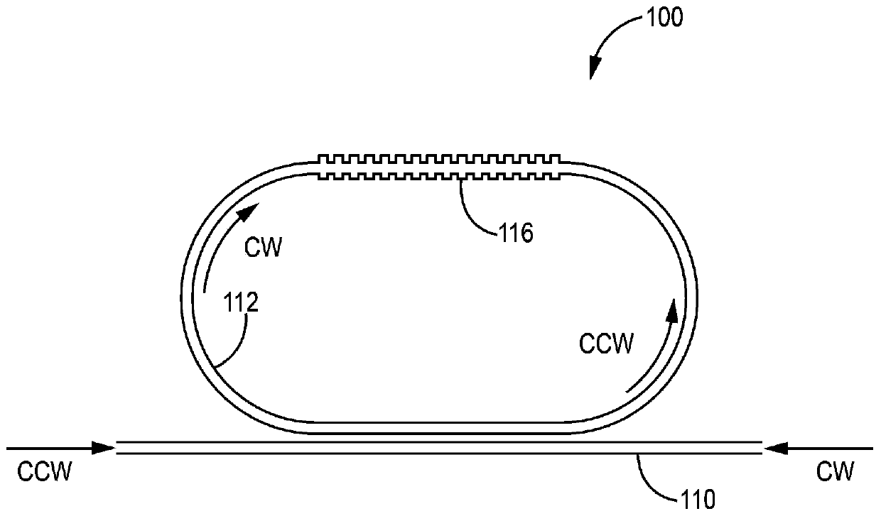
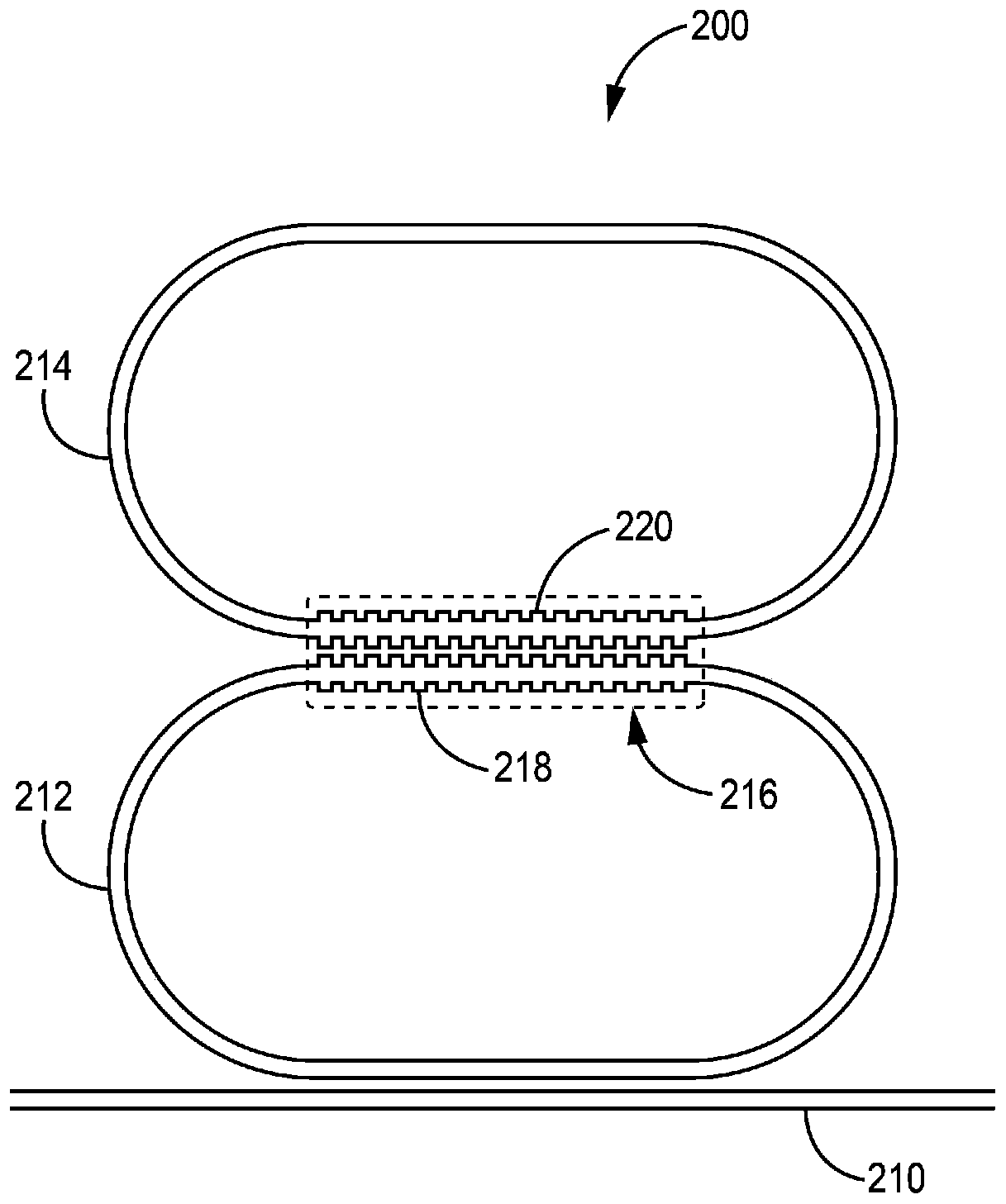
[0033] Embodiment 1 includes an optical frequency comb generator device comprising: a bus waveguide; at least a first optical ring resonator optically coupled to the bus waveguide; and at least a first grating, the first A grating is positioned on the first optical ring resonator opposite the bus waveguide; wherein the first optical ring resonator and the first grating are configured to generate counterpropagating optical frequency combs offset from each other over a controllable bandwidth.

Embodiment 2

[0034] Embodiment 2 includes the device of embodiment 1, wherein the first grating comprises a Bragg grating that is inverse engineered to have a uniform grating strength over a given wavelength range.

Embodiment 3

[0035] Embodiment 3 includes the device of any one of Embodiments 1 to 2, wherein when two counter-propagating beams are coupled into the device through the bus waveguide, the first grating operates to convert the inverse of the first optical ring resonator to The clockwise (CCW) propagation mode is coupled to the clockwise (CW) propagation mode.


PUM


Abstract

The invention is entitled RF frequency synthesis based on offset optical frequency combs in ring resonators. The invention discloses an optical frequency comb generator device. In one implementation,the optical frequency comb generator device comprises a bus waveguide, at least a first optical ring resonator optically coupled to the bus waveguide, and at least a first grating located on the firstoptical ring resonator opposite from the bus waveguide. The first optical ring resonator and the first grating are configured to generate counter-propagating optical frequency combs that are offset from each other at a controllable bandwidth.

Description

Background technique [0001] Devices capable of generating stable low noise radio frequency (RF) signals in the MHz to GHz range are highly sought after for a large number of communication applications. Currently, optical frequency combs offer one of the most efficient ways to generate ultra-low-noise RF signals. In order for an optical frequency comb to work, the comb needs to be cross-octave to down-convert from a higher optical frequency to a lower optical frequency. For example, it is the state of the art to use an optical frequency comb spanning an entire octave to generate RF signals. However, this process is less efficient because most of the signal is unused and thus requires a high power optical pump. Contents of the invention [0002] The invention discloses an optical frequency comb generator device. In one implementation, an optical frequency comb generator device includes a bus waveguide, at least a first optical ring resonator optically coupled to the bus wav...

Claims


Application Information

Patent Timeline
IPC IPC(8): G02B6/293
CPCG02B6/29338G02B6/29379G02F2/02G02F2203/56G02F1/3132G02F2203/15G02B2006/12107G02B6/29323
Inventor 马修·韦德·帕克特尼尔·A·克吕格尔吴剑峰
Owner HONEYWELL INT INC
Why Eureka
Try Eureka