Touch sensing method for display with touch device

A touch display device and touch sensing technology, applied in the input/output process of data processing, instruments, electrical digital data processing, etc., can solve the problem of limited vertical blank interval time and insufficient vertical blank interval time of the display panel, etc. question

Active Publication Date: 2019-12-10
ELAN MICROELECTRONICS CORPORATION
View PDF8 Cites 1 Cited by
  • Summary
  • Abstract
  • Description
  • Claims
  • Application Information

AI Technical Summary

Problems solved by technology

However, the vertical blank interval of the display panel is limited. For the current multi-tasking and time-sharing sensing of different types of touch objects (such as active stylus, passive stylus, fingers, etc.), the existing Not enough vertical blank space

Method used


Image

  • Touch sensing method for display with touch device
  • Touch sensing method for display with touch device
  • Touch sensing method for display with touch device

Examples


Embodiment Construction

[0033] The technical means adopted by the present invention to achieve the intended purpose of the invention will be further described below in conjunction with the drawings and the embodiments of the present invention.

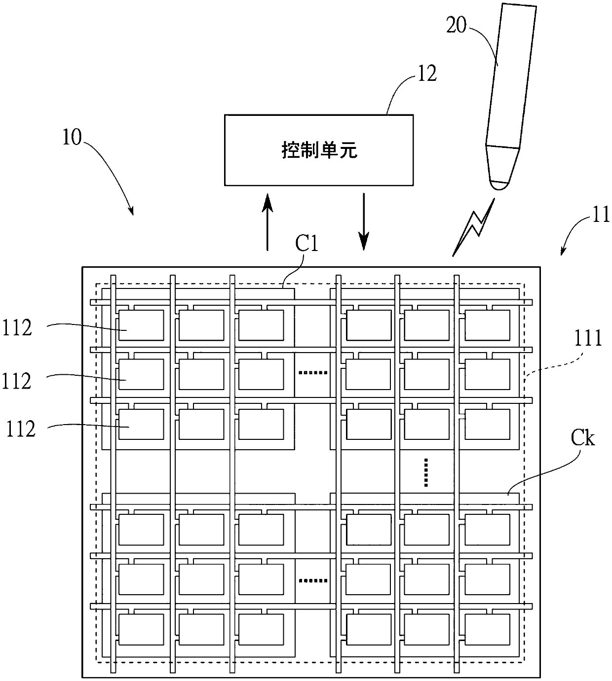
[0034] see figure 1 and figure 2 As shown, the touch display device 10 of the present invention mainly includes a display panel 11 and a control unit 12 , the control unit 12 is electrically connected to the display panel 11 for controlling the display panel 11 to display images or touch detection. The display panel 11 mainly includes a plurality of thin film transistors (not shown), a common electrode layer 111 and a plurality of pixel electrodes 112 . In this embodiment, the common electrode layer 111 includes a plurality of common electrodes C arranged in a matrix 1 ~C K ; Each common electrode C 1 ~C K Corresponding to h display pixels, where h is a positive integer greater than 1. For the convenience of explaining the technical content of this emb...


PUM


Abstract

The invention relates to a touch sensing method for a display with touch device having an image display period, which includes multiple execution time sections. Each execution time section has a display time division and a blank time division. A display procedure is executed in each display time division. A communicating procedure is executed in one of the blank time division. In the communicatingprocedure, an uplink signal is provided by the common electrodes for a first object to receive. Thus, the display with touch device has more time to detect more different kinds of touch objects.

Description

technical field [0001] The present invention relates to a touch sensing method in a touch display device, in particular to a touch display device capable of using a horizontal blank space to perform a touch procedure. Background technique [0002] At present, the in-cell touch display device (In-Cell Touch Display Device) uses the common electrode layer of the original display panel as the touch sensing electrode, so most of them adopt time-sharing display driving and touch scanning methods. The time-sharing display driving and touch scanning method divides each image display driving cycle of the original display panel (taking the display frequency as 60 Hz as an example, the image display driving cycle is 16.67 ms) into a display time period and a touch control time period; The touch time period corresponds to the vertical blanking interval (Vertical Blanking Interval, VBI) time of the display panel; therefore, it will not affect the image display of the display panel. Dur...

Claims


Application Information

Patent Timeline
Patent Type & Authority Applications(China)
IPC IPC(8): G06F3/0488
CPCG06F3/0488G06F3/0412G06F3/04184G06F3/0443G06F3/044G06F3/0416
Inventor 陈俊宇谢坤霖
Owner ELAN MICROELECTRONICS CORPORATION
Why Eureka
Try Eureka