A wire clip for spacer rods for splitting wires on an empty frame

A technology of splitting conductors and spacers, which is applied in the direction of the device for maintaining the distance between parallel conductors, can solve the problems of reducing the service life of wire clips and wires, metal fatigue and wear of wires and wire clips, and achieves weakening damage, reducing amplitude, The effect of reducing wear

Active Publication Date: 2020-07-24
TORCH ELECTRICAL GRP
View PDF6 Cites 0 Cited by
  • Summary
  • Abstract
  • Description
  • Claims
  • Application Information

AI Technical Summary

Problems solved by technology

[0003] see figure 1 , the spacer bar divides the conductor into multiple segments. In fact, due to the long length of the conductor, the conductor in the segment will swing to a certain extent. Since the connection between the clamp and the conductor is a hard connection, the conductor flaps The final stress point is the connection point between the clamp and the wire. Long-term swinging can easily cause metal fatigue of the wire and clamp, reducing the service life of the clamp and wire.
[0004] Further, since the spacer frame has a certain area, when the wind direction is not horizontal or vertical to the spacer, the spacer frame will be subjected to a twisting force, and the spacer will also transmit the pulling force of other sub-conductors in an uncertain direction, Since the frame of the spacer bar and the clamp are usually rigidly connected, the final point of stress is the contact point between the clamp and the wire, which further accelerates the wear and tear of this place

Method used


Image

  • A wire clip for spacer rods for splitting wires on an empty frame
  • A wire clip for spacer rods for splitting wires on an empty frame
  • A wire clip for spacer rods for splitting wires on an empty frame

Examples


Embodiment Construction

[0020] The following will clearly and completely describe the technical solutions in the embodiments of the present invention with reference to the accompanying drawings in the embodiments of the present invention. Obviously, the described embodiments are only some, not all, embodiments of the present invention. Based on the embodiments of the present invention, all other embodiments obtained by persons of ordinary skill in the art without making creative efforts belong to the protection scope of the present invention.

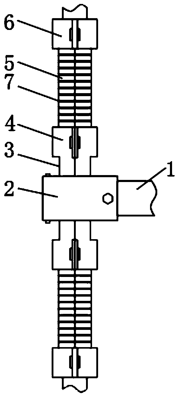
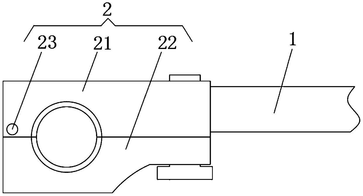
[0021] see Figure 2-5 , a wire clamp for spacer rods for splitting wires on an empty frame, comprising a spacer frame body 1, the spacer frame body 1 is fixedly connected with a first jacket 2, the first jacket 2 is sleeved with a load-bearing sleeve 3, the first Jacket 2 comprises upper clamping plate 21, lower clamping plate 22 and hinge shaft 23, and upper clamping plate 21 is fixedly connected with spacer bar frame body 1, and the top of upper clamping pl...


PUM


Abstract

The invention relates to the technical field of power transmission equipment, and discloses a wire clamp for an overhead split wire spacer. The wire clamp comprises a spacer frame body, wherein the spacer frame body is fixedly connected with a first clamp sleeve, the first clamp sleeve is sleeved with a force bearing sleeve, and two ends of the force bearing sleeve are fixedly connected with firstfixing sleeves. According to the wire clamp for the overhead split wire spacer, when a wire swings, the acting force between the wire and the wire clamp is dispersed on each section of a force equalizing sleeve, so that the acting force of a single point is reduced. Meanwhile, two sections are mutually contacted and mutually supported, so that the swinging amplitude of the wire is reduced. In addition, a connecting elastic band between the two sections can also consume the swinging energy, so that the swing amplitude is further reduced, the damage effect caused by repeated swing is weakened,the service life of the wire and the wire clamp is prolonged. Meanwhile, the acting force of the first fixing sleeve on the wire is dispersed on a plurality of acting points through the force equalizing sleeve, so that the effect of force between the spacer and the wire is reduced.

Description

technical field [0001] The invention relates to the technical field of electric transmission equipment, in particular to a wire clip for spacer rods for splitting wires on an empty frame. Background technique [0002] Split conductor refers to splitting a conductor into multiple sub-conductors with smaller cross-sectional areas. The distance between sub-conductors is 0.2-0.5 meters. The reactance of the wire is reduced, and the voltage drop is reduced. At the same time, the thinner wire also reduces the influence of breeze vibration and improves the shockproof effect of the overhead line. [0003] see figure 1 , the spacer bar divides the conductor into multiple segments. In fact, due to the long length of the conductor, the conductor in the segment will swing to a certain extent. Since the connection between the clamp and the conductor is a hard connection, the conductor flaps When the final stress point is the connection point between the clamp and the wire, the long-ter...

Claims


Application Information

Patent Timeline
Patent Type & Authority Patents(China)
IPC IPC(8): H02G7/12
CPCH02G7/12
Inventor 贺绍喜
Owner TORCH ELECTRICAL GRP
Why Eureka
Try Eureka