
Micro-pressure cooker with one-key control function

A technology of functions and pot lids, which is applied in pressure cookers, household utensils, kitchen utensils, etc., can solve the problems of turning off the small firepower, complex structure, and the pot and lid can't be fastened, so as to reduce the problem of clogging, simple operation, and prompt air pressure Effect

Pending Publication Date: 2019-12-13
XINXING XIANFENG STAINLESS STEEL PROD MFGR CO LTD
View PDF0 Cites 5 Cited by
  • Summary
  • Abstract
  • Description
  • Claims
  • Application Information

AI Technical Summary

Problems solved by technology

[0002] The opening and closing methods of the low-pressure cookers on the market are relatively complicated. Some use the misalignment between the lid and the pot body to complete the opening and closing operation, and some are too complicated for the user to open and close. understand its application
In some low-pressure cookers, the lid and the pot are half-opened and closed easily during use, causing the pot and the lid to fail to buckle, resulting in pressure leakage in the pot.
There are also some low-pressure cookers that turn off the firepower because they do not pay attention to the excessive pressure in the pot during cooking, resulting in safety accidents.

Method used


Image

  • Micro-pressure cooker with one-key control function
  • Micro-pressure cooker with one-key control function
  • Micro-pressure cooker with one-key control function

Examples


Embodiment

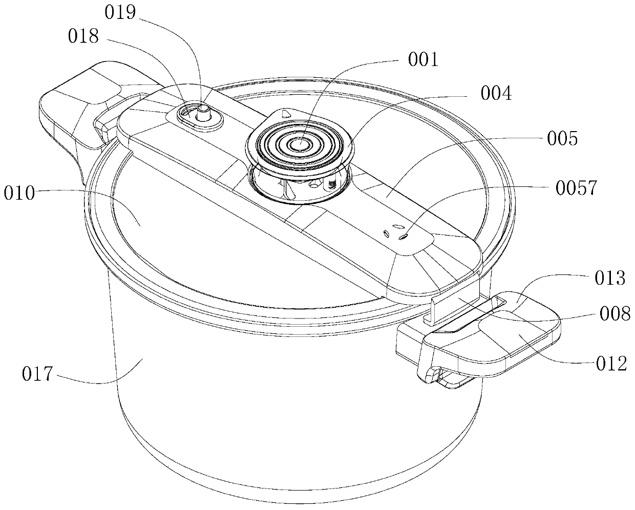
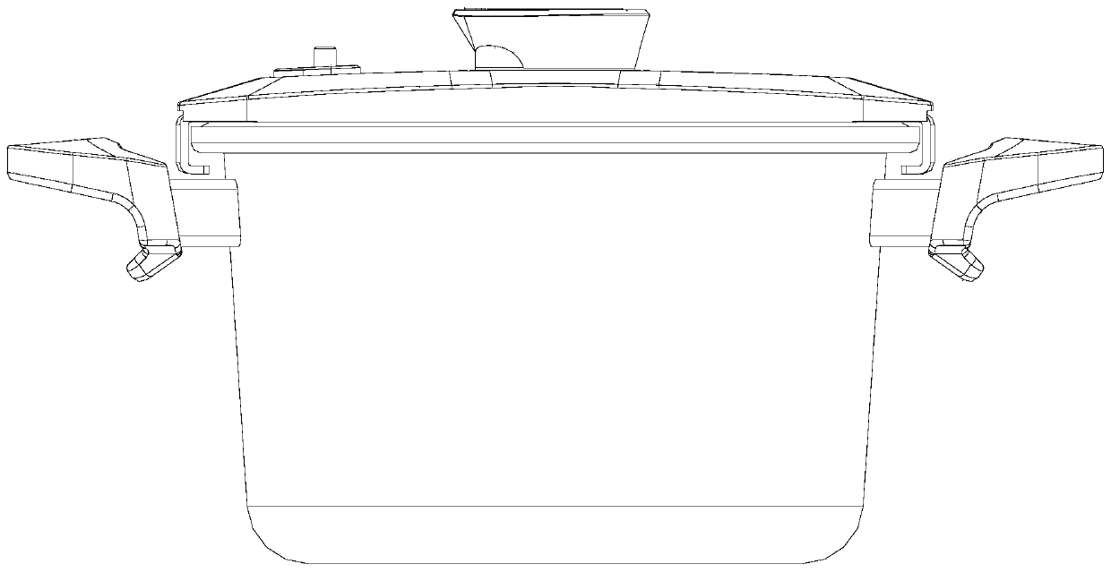
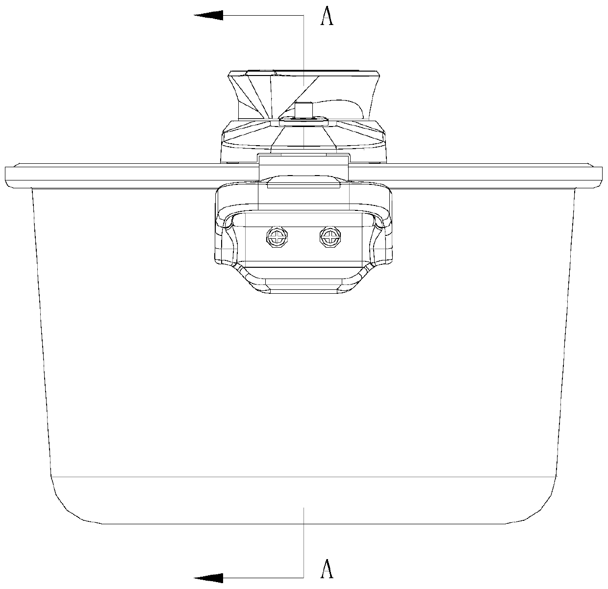
[0050] refer to Figure 1 to Figure 31 , is a micro-pressure cooker with one-button control function, including a pot body 017 and a pot cover 010. 004 of the button cover, there is an exhaust push rod 020 between the panel 005 and the pot cover 010, a set of slider buckles 008 for fastening or loosening the pot cover 010 and the pot body 017, and a pair of side slider buckles for The adjustment assembly for adjusting the pressure in the pot, and the air valve assembly for exhaust; the slider buckle 008 is connected with the knob cover 004 and is controlled by the slider buckle 008 to fasten or loosen the connection between the pot cover 010 and the pot body 017 Side; the adjustment assembly includes the first air valve lower part 023, the steel ball 007, and the air valve spring 006 that penetrate up and down through the first air hole 0231; the first air valve lower part 023 is installed on the pot cover 010, and the steel ball 007 is placed On the first air hole 0231 of th...


PUM


Abstract

The invention discloses a micro-pressure cooker with a one-key control function. The micro-pressure cooker comprises a cooker body and a cooker cover, wherein a panel and a rotating button cover are arranged on the upper side surface of the cooker cover, and an exhaust push rod, a group of sliding block buckles for fastening or loosening a group of opposite side edges of the cooker cover and the cooker body, an adjusting assembly for adjusting the pressure in the cooker and an air valve assembly for exhausting are arranged between the panel and the cooker cover; the sliding block buckles are connected with the rotating button cover and the rotating button cover controls the sliding block buckles to fasten or loosen the side edges of the cooker cover and the cooker body; the adjusting assembly comprises a first air valve lower piece, a steel ball and an air valve spring, wherein the first air valve lower piece penetrates through a first air hole from top to bottom, the steel ball is arranged in the first air hole, and the lower part of the first air hole communicates with the inside of the cooker; and the lower end of the air valve spring presses the steel ball, and the upper end ofthe air valve spring pushes against the panel. The micro-pressure cooker can control the opening and closing of the cooker cover and the adjustment of the pressure in the cooker by one key, and is simple in operation; the rotating button cover is arranged, so that the functions of air locking increase or air exhaust and pressure relief can be realized; and the exhaust design and the pressure condition can be visually observed, and the blockage problem in the cooking process is reduced.

Description

technical field [0001] The invention relates to the technical field of kitchen cooking utensils, in particular to a micro-pressure cooker with a one-button control function. Background technique [0002] The operation of opening and closing the pressure cooker on the market is relatively complicated. Some use the dislocation between the lid and the body of the pot to complete the opening and closing operation, and some require the cooperation of both hands to complete the opening and closing operation. Some are too complicated for the user to open and close. understand its application. Some low-pressure cookers are prone to the lid and the pot being in a half-open and closed state during use, causing the pot and the lid to fail to buckle, resulting in pressure leakage in the pot. There are also some low-pressure cookers that turn off the firepower because they do not pay attention to the excessive pressure in the pot during cooking, resulting in safety accidents. Contents...

Claims


Application Information

Patent Timeline
IPC IPC(8): A47J27/00A47J27/08A47J36/00A47J36/06A47J36/10A47J36/38
CPCA47J27/002A47J27/08A47J36/00A47J36/06A47J36/10A47J36/38
Inventor 李凌瀚黄志荣黄秋萍伍尚凯梁松伟潘德赢吴金洋冯荣基李广彬刘金焕梁毅刘锦雄
Owner XINXING XIANFENG STAINLESS STEEL PROD MFGR CO LTD
Learn More