A thin wire cutting device for construction

A thin iron wire, a technology used in construction, applied in the field of cutting equipment, can solve problems such as low work efficiency, affecting work, troublesome operation, etc.

Active Publication Date: 2021-05-14
赣州市榕盛新型建材有限公司
View PDF5 Cites 1 Cited by
  • Summary
  • Abstract
  • Description
  • Claims
  • Application Information

AI Technical Summary

Problems solved by technology

[0002] During building construction, a large number of thin iron wires will be used, but the thin iron wires are coiled at the beginning, and the thin iron wires need to be cut off before use, so that people can use them during construction. Usually, people use wire cutters to cut the thin iron wires. When cutting the wire, it is necessary to continuously turn the wire pliers. After a long time, the hands are easy to be sore and affect the follow-up work, and because people need to pull the thin wire to move, it is easy to cause the length of the cut wire to be inconsistent, so people will use a ruler to measure the length of the thin wire. Measure it well, then cut it off with wire cutters, and take a break after working for a while. This operation is troublesome and the work efficiency is low.

Method used


Image

  • A thin wire cutting device for construction
  • A thin wire cutting device for construction
  • A thin wire cutting device for construction

Examples


Embodiment 1

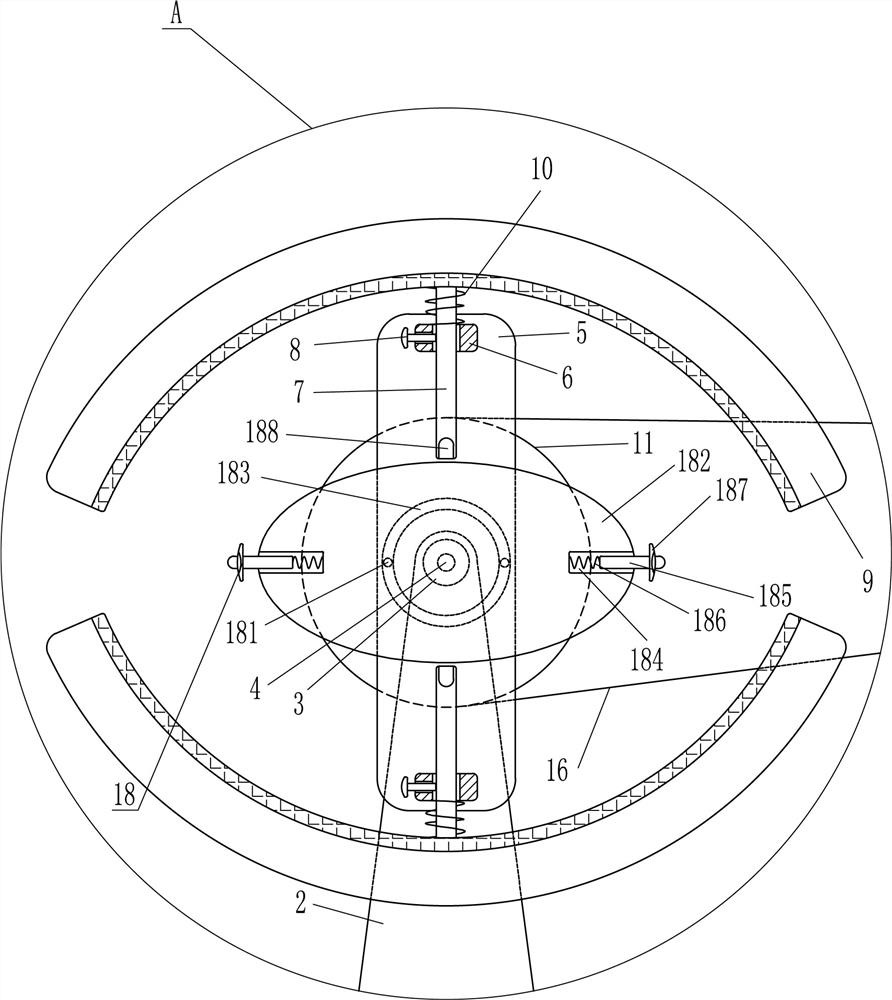
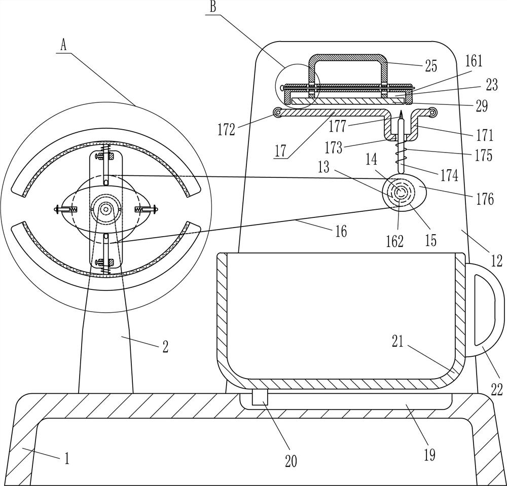
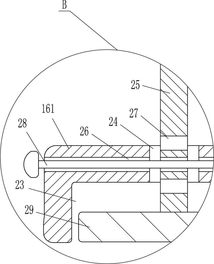
[0016] A thin wire cutting device for construction, such as Figure 1-2 As shown, it includes a base 1, a support plate 2, a first bearing seat 3, a first rotating shaft 4, a movable plate 5, a first guide sleeve 6, a first guide rod 7, a fastening bolt 8, an arc plate 9, the first One spring 10, the first pulley 11, the rear side plate 12, the first motor 13, the second rotating shaft 14, the second pulley 15, the flat belt 16, the fixed block 161, the second bearing seat 162 and the cutting device 17, the top of the base 1 A support plate 2 is arranged at the rear of the left side, and the base 1 is connected with the support plate 2 through bolt connection. The upper part of the support plate 2 is embedded with a first bearing seat 3, and the first bearing seat 3 is provided with a first rotating shaft 4. The front side of a rotating shaft 4 is provided with a movable plate 5, and the upper and lower sides of the movable plate 5 front are provided with a first guide sleeve ...

Embodiment 2

[0018] A thin wire cutting device for construction, such as Figure 1-3 As shown, it includes a base 1, a support plate 2, a first bearing seat 3, a first rotating shaft 4, a movable plate 5, a first guide sleeve 6, a first guide rod 7, a fastening bolt 8, an arc plate 9, the first One spring 10, the first pulley 11, the rear side plate 12, the first motor 13, the second rotating shaft 14, the second pulley 15, the flat belt 16, the fixed block 161, the second bearing seat 162 and the cutting device 17, the top of the base 1 A support plate 2 is arranged at the left side rear, and a first bearing seat 3 is embedded in the upper part of the support plate 2. A first rotating shaft 4 is arranged in the first bearing seat 3. A movable plate 5 is arranged on the front side of the first rotating shaft 4. The movable plate 5. The first guide sleeve 6 is provided on the upper and lower sides of the front side, the first guide rod 7 is arranged inside the first guide sleeve 6, and the ...

Embodiment 3

[0021] A thin wire cutting device for construction, such as Figure 1-3 As shown, it includes a base 1, a support plate 2, a first bearing seat 3, a first rotating shaft 4, a movable plate 5, a first guide sleeve 6, a first guide rod 7, a fastening bolt 8, an arc plate 9, the first One spring 10, the first pulley 11, the rear side plate 12, the first motor 13, the second rotating shaft 14, the second pulley 15, the flat belt 16, the fixed block 161, the second bearing seat 162 and the cutting device 17, the top of the base 1 A support plate 2 is arranged at the left side rear, and a first bearing seat 3 is embedded in the upper part of the support plate 2. A first rotating shaft 4 is arranged in the first bearing seat 3. A movable plate 5 is arranged on the front side of the first rotating shaft 4. The movable plate 5. The first guide sleeve 6 is provided on the upper and lower sides of the front side, the first guide rod 7 is arranged inside the first guide sleeve 6, and the ...


PUM


Abstract

The invention relates to a cutting device, in particular to a fine iron wire cutting device for construction. Therefore, the technical problem of the present invention is to provide a thin iron wire cutting device for construction that can replace manual cutting of thin iron wires, saves more labor, avoids hand soreness affecting follow-up work, and has the same length of cut thin iron wires. The technical embodiment of the present invention is: a thin iron wire cutting device for construction, including a base, a support plate, a first bearing seat, a first rotating shaft, a movable plate, a first guide sleeve, a first guide rod, etc.; There are support plates at the rear of the side. In the present invention, the thin iron wire rolls are fixed on the upper and lower arc-shaped plates, and the first motor is started to rotate forward, so that the head end of the thin iron wire can continuously move to the right, and at the same time, the cutting knife can be moved up and down to move to the right. The moving thin wire is cut off without the need for people to use wire cutters to cut the thin wire, which saves more effort, avoids sore hands, and also makes the length of the cut thin wire consistent.

Description

technical field [0001] The invention relates to a cutting device, in particular to a fine iron wire cutting device for construction. Background technique [0002] During building construction, a large number of thin iron wires will be used, but the thin iron wires are coiled at the beginning, and the thin iron wires need to be cut off before use, so that people can use them during construction. Usually, people use wire cutters to cut the thin iron wires. When cutting the wire, it is necessary to continuously turn the wire pliers. After a long time, the hands are easy to be sore and affect the follow-up work, and because people need to pull the thin wire to move, it is easy to cause the length of the cut wire to be inconsistent, so people will use a ruler to measure the length of the thin wire. Measure it well, then cut it off with wire cutters, and then take a rest after working for a while. This operation is troublesome and the work efficiency is low. Contents of the inve...

Claims


Application Information

Patent Timeline
Patent Type & Authority Patents(China)
IPC IPC(8): B21F11/00
CPCB21F11/00
Inventor 谢浩
Owner 赣州市榕盛新型建材有限公司
Why Eureka
Try Eureka