
Automatic welding machine

An automatic welding machine and frame technology, which is applied in welding equipment, auxiliary welding equipment, welding/cutting auxiliary equipment, etc., can solve the problems of high labor intensity, inaccurate welding position, and low efficiency

Inactive Publication Date: 2019-12-13
安吉腾飞家具有限公司
View PDF0 Cites 2 Cited by
  • Summary
  • Abstract
  • Description
  • Claims
  • Application Information

AI Technical Summary

Problems solved by technology

[0004] The purpose of the present invention is to provide an automatic welding machine to solve the problems of inaccurate welding position, unreliable quality, low efficiency and high labor intensity in the prior art proposed in the above-mentioned background technology

Method used


Image

  • Automatic welding machine
  • Automatic welding machine
  • Automatic welding machine

Examples


Embodiment Construction

[0023] The following will clearly and completely describe the technical solutions in the embodiments of the present invention with reference to the accompanying drawings in the embodiments of the present invention. Obviously, the described embodiments are only some, not all, embodiments of the present invention. The specific embodiments described here are only used to explain the present invention, not to limit the present invention. Based on the embodiments of the present invention, all other embodiments obtained by persons of ordinary skill in the art without making creative efforts belong to the protection scope of the present invention.

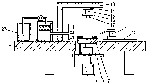
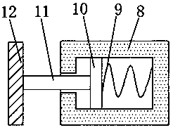
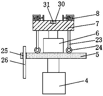
[0024] The present invention provides such figure 1 and image 3 The automatic welding machine shown includes a frame 1, a linear sliding table 2 is installed on the top side of the frame 1, a welding torch 3 is installed on the sliding table of the linear sliding table 2, and a hydraulic cylinder 4 is installed on the bottom of the fram...


PUM


Abstract

The invention discloses an automatic welding machine. The automatic welding machine comprises a rack, a linear sliding table is installed on one side of the top of the rack, a welding gun is installedon a sliding table body of the linear sliding table, a hydraulic cylinder is installed at the bottom of the rack, a fixed plate is welded to an output shaft of the hydraulic cylinder, a motor is mounted at the top of the fixed plate, and a rotating plate is fixedly connected to an output shaft of the motor. The automatic welding machine is mainly composed of the rack, the linear sliding table, the hydraulic cylinder, the motor, a support and other components, in the welding process, a base of a bar chair is placed on the rotating plate, the base bears squeezing force of a spring in a cylinderbody and is fixed to the rotating plate, then a steel pipe of the bar chair is inserted into a sleeve at the bottom of a top plate, and the base is driven by the hydraulic cylinder to move upwards, so that the base and the steel pipe are in butt joint and clamped between the top plate and the rotating plate, and the linear sliding table drives the welding gun to weld the base and the steel pipe.Meanwhile, the motor drives the base to rotate, automatic welding of the bar chair is facilitated, and the welding quality and efficiency are improved.

Description

technical field [0001] The invention belongs to the technical field of automatic welding mechanisms, and in particular relates to automatic welding machines. Background technique [0002] Most of the bar chairs on the market now consist of an upper seat surface and lower legs, and the load-bearing support components of the lower legs are also varied. For example: a bar chair with a chassis needs a tray, a connecting piece, and an air rod to support the load; an iron frame chair needs an iron frame and connecting iron to fix it. [0003] In the production and processing of bar chairs, it is usually necessary to weld the tray and the connected body. However, in the prior art, people usually use manual welding to weld the tray and the connected body. Accurate, unreliable quality, and low efficiency, labor-intensive. Contents of the invention [0004] The object of the present invention is to provide an automatic welding machine to solve the problems of inaccurate welding po...

Claims


Application Information

Patent Timeline
Patent Type & Authority Applications(China)
IPC IPC(8): B23K37/047B23K37/00
CPCB23K37/00B23K37/047
Inventor 李枫林
Owner 安吉腾飞家具有限公司
Learn More