Box girder automatic welding device and using method

An automatic welding and box beam technology, applied in welding equipment, welding equipment, auxiliary devices, etc., can solve problems such as failure to achieve fixation and support, the fixation mechanism cannot be adjusted, and the welding of the fixation mechanism is omitted. Simple, convenient disassembly, and the effect of improving welding quality

Active Publication Date: 2020-09-08
TIANJIN SINO GERMAN VOCATIONAL TECHNICAL COLLEGE
View PDF6 Cites 0 Cited by
  • Summary
  • Abstract
  • Description
  • Claims
  • Application Information

AI Technical Summary

Problems solved by technology

In the prior art, either the fixing mechanism is set outside the cover plate or the fixing mechanism is set inside the box girder, but the fixing mechanism cannot be adjusted after it is fixed, that is to say, if the subsequent If the fixing mechanism is deformed or destroyed, the effect of fixing and supporting will not be achieved, and the fixing mechanism in the prior art cannot achieve the purpose of dynamic adjustment during welding; in addition, because the fixing mechanism in the prior art is arranged at two Therefore, when welding between plates, the welding between the plates of the fixing mechanism will be missed, which will seriously affect the welding quality. Repair welding after removing the fixing mechanism will also affect the welding. quality
At the same time, in the prior art, the installation and disassembly of the box girder fixing device are more troublesome, and the degree of automation is low

Method used


Image

  • Box girder automatic welding device and using method
  • Box girder automatic welding device and using method
  • Box girder automatic welding device and using method

Examples


Embodiment Construction

[0052] In order to enable those skilled in the art to better understand the technical solutions of the present invention, the present invention will be further described in detail below in conjunction with the accompanying drawings and preferred embodiments.

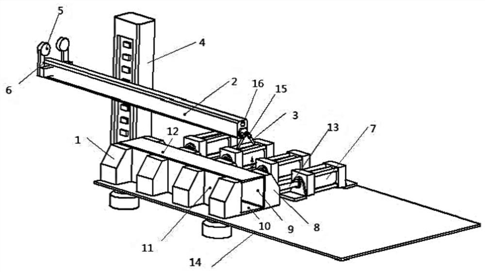
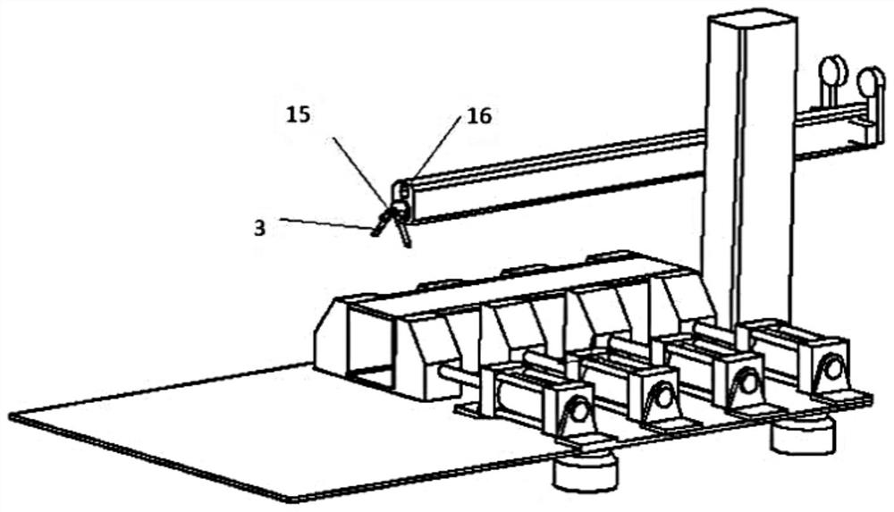
[0053] Figure 1-2 It shows a box girder automatic welding device, including a box girder fixing unit and a welding unit for fixing the box girder;

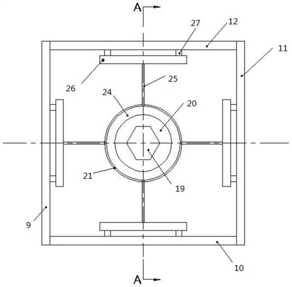
[0054] The box-shaped beam fixing unit includes a base 14, a fixed clamping block 1 arranged on one side of the base 14, a movable clamping block 8 arranged at the other end of the base, and a fixed clamping block 8 arranged inside the box-shaped beam. The auxiliary carriage 17; the movable clamping block 8 is connected with the piston rod 13 of the cylinder 7; the box beam includes a cover plate 12, a web 11, a bottom plate 10 and a partition 9;

[0055] Described welding unit comprises welding wire gun support arm 2, is arranged on the welding wire gun 3 on described wel...


PUM


Abstract

The invention belongs to the field of welding, and particularly relates to an automatic welding device for a box girder and an application method thereof. The automatic welding device for the box girder comprises a box girder fixing unit and a welding unit for fixing the box girder; the box girder fixing unit comprises a base, a fixed clamping block on one side of the base, a movable clamping block on the other end of a bottom plate and an auxiliary sliding frame inside the box girder; the welding unit comprises a welding wire gun supporting arm, a welding wire gun on the welding wire gun supporting arm and a supporting block used to support the welding wire gun supporting arm; one end of the welding wire gun supporting arm is provided with a mating hole engaging with the auxiliary slidingframe, the auxiliary sliding frame can dynamically adjust a box girder support during welding. The automatic welding device for the box girder and the application method thereof have the advantages of simple structure and easy adjustment and can conveniently automatically weld the box girders of various sizes, so that the labor intensity of box girder welders is reduced.

Description

technical field [0001] The invention belongs to the field of welding, and in particular relates to an automatic welding device for a box girder and a use method thereof. Background technique [0002] Welding is a manufacturing technology, which is developed on the basis of modern industry to meet the needs of industrial development, and directly serves the machinery manufacturing industry. The large structural parts in many equipment are almost all welded structures. With the advancement of science and technology, the scale of production is expanding day by day, and the welded structural parts are developing towards large and super large. This requires various welding machines with higher quality, better performance and more functions for welding production. [0003] The cross-sectional shape of the box girder is the same as that of the usual box section, and is generally composed of a cover plate, a web plate, a bottom plate and a partition. At present, there are many equ...

Claims


Application Information

Patent Timeline
Patent Type & Authority Patents(China)
IPC IPC(8): B23K31/02B23K37/04
CPCB23K31/02B23K37/0426
Inventor 武晋胡海朝王占辉谢久明毕彦
Owner TIANJIN SINO GERMAN VOCATIONAL TECHNICAL COLLEGE
Why Eureka
Try Eureka