Auxiliary tool, welding system with auxiliary tool and welding method

A technology of auxiliary tooling and welding system, applied in the field of steel structure manufacturing, can solve the problems of increasing the difficulty of rail installation, welding limitation of welding trolley, manual handling of rails, etc., to reduce labor intensity, improve efficiency, and uniform welding angle size. Effect

Inactive Publication Date: 2019-04-19
SHANGHAI ZHENHUA HEAVY IND
View PDF6 Cites 0 Cited by
  • Summary
  • Abstract
  • Description
  • Claims
  • Application Information

AI Technical Summary

Problems solved by technology

In order to improve welding efficiency, automatic welding can be carried out by welding trolley. Although the welding efficiency is high, there are still some problems. Welding within the length range, the disadvantage is that it needs to be equipped with various lengths of rails for combination, the box reinforcement ribs pass through holes and the process holes in the middle of the partition will increase the difficulty of rail installation, the rails need to be manually moved and fixed, and the rails are larger than 2m (2) The traditional trackless (that is, wheeled) welding trolley is adopted, and the wheel base is relatively large. Usually, it is necessary to use the partition as the walking tread (the height of the reinforcement rib is not enough), and the reinforcement rib base for walking
However, the existence of the through hole of the reinforcing rib of the box and the process hole in the middle of the partition makes it difficult for the trolley to continuously walk and weld, which limits the welding of the welding trolley

Method used


Image

  • Auxiliary tool, welding system with auxiliary tool and welding method
  • Auxiliary tool, welding system with auxiliary tool and welding method
  • Auxiliary tool, welding system with auxiliary tool and welding method

Examples


Embodiment Construction

[0059] The implementation of the present invention will be illustrated by specific specific examples below, and those skilled in the art can easily understand other advantages and effects of the present invention from the content disclosed in this specification. Although the description of the present invention will be presented in conjunction with a preferred embodiment, it does not mean that the features of the invention are limited to this embodiment. On the contrary, the purpose of introducing the invention in conjunction with the embodiments is to cover other options or modifications that may be extended based on the claims of the present invention. The following description contains numerous specific details in order to provide a thorough understanding of the present invention. The invention may also be practiced without these details. Also, some specific details will be omitted from the description in order to avoid obscuring or obscuring the gist of the present invent...


PUM


Abstract

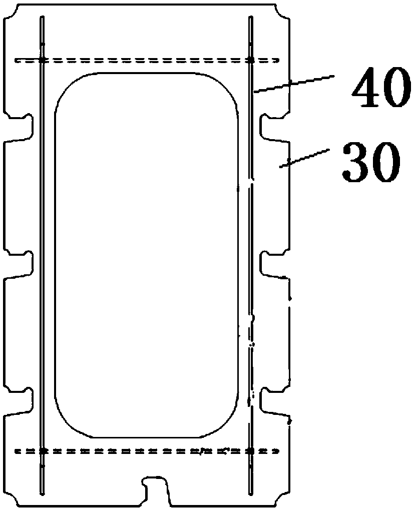
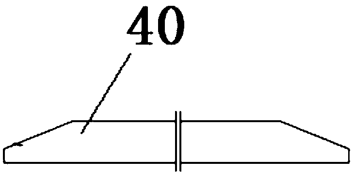
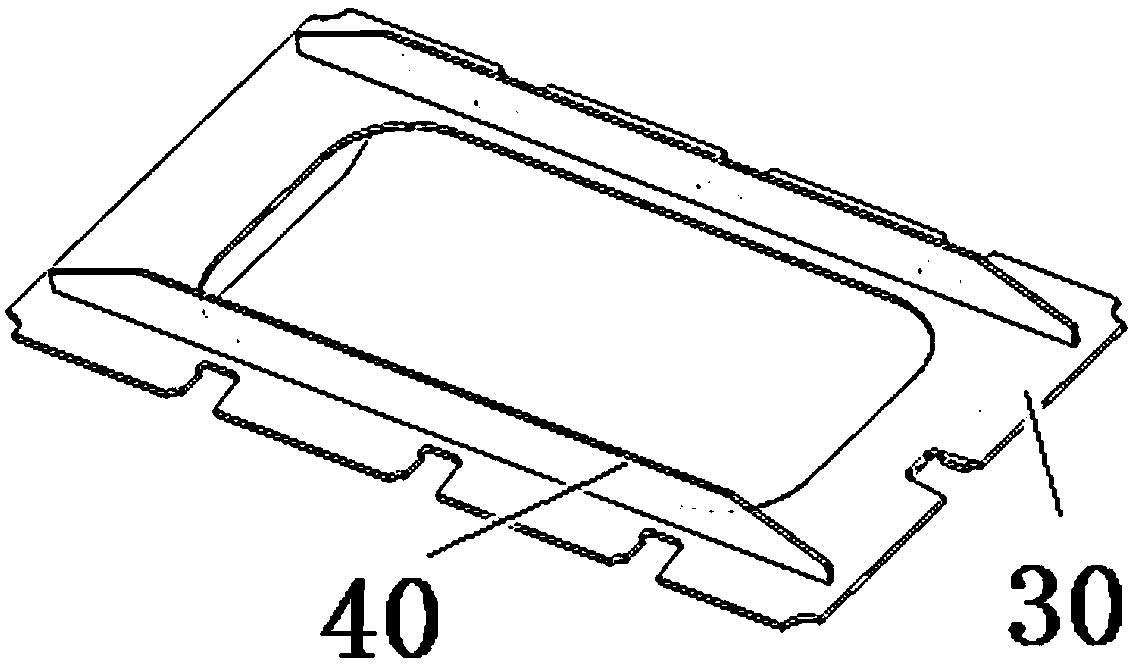
The invention provides an auxiliary tool, a welding system with the auxiliary tool and a welding method. The auxiliary tool is used for welding a port crane box beam partition plate and reinforcing ribs, the auxiliary tool comprises a base face plate which is used for cooperating with the partition plate in a coplanar mode, a pedal face plate which is connected with the base face plate and is usedfor cooperating with the reinforcing ribs in a coplanar mode, and a fixing portion which is connected with the pedal face plate and is used for being connected with the partition plate. Through the auxiliary tool, the partition plate can be extended, when a trolley walks to the end, trolley wheels can be supported to walk, so that the reinforcing ribs are extended, when the trolley walks to the end, the trolley is allowed for attracting and walking, so that rapid installing and positioning are facilitated, full-length welding is achieved, welding of the welding trolley is facilitated, so thatthe efficiency of the welding trolley is improved; through the welding system, trolley automatic welding of the partition plate and the reinforcing ribs can be realized, the welding angle is uniformin size, the welding seam is continuous, the weld seam grinding workload is remarkably reduced, continuous welding can be realized, the labor intensity is remarkably reduced, and the welding efficiency is improved.

Description

technical field [0001] The invention relates to the field of steel structure manufacturing, in particular to an auxiliary tooling, a welding system and a welding method with the same. Background technique [0002] The bulkhead is an important part of the box girder structure of port cranes (shore container cranes, rail cranes and gantry cranes, etc.), with a large number and similar structures. For the bulkhead at the part of the box girder with severe stress conditions (such as the position of the gusset plate), in order to improve the strength and deformation resistance of the bulkhead, reinforcement ribs are usually used for structural reinforcement. The structural cooperation between the bulkhead and the rib is as follows: figure 1 and image 3 As shown, the structure of the stiffener is as figure 2 shown. [0003] The reinforcing rib and the partition are connected by fillet welds, the design welding angle size is generally 6mm, 8mm or 10mm, the length of the reinfo...

Claims


Application Information

Patent Timeline
Patent Type & Authority Applications(China)
IPC IPC(8): B23K37/02B23K37/04B23K37/00
CPCB23K37/00B23K37/0211B23K37/0426
Inventor 赵德龙刘建波王桂军牛曰海包孔冯健倪春华杜渝
Owner SHANGHAI ZHENHUA HEAVY IND
Why Eureka
Try Eureka