Automobile safety belt limiting device

A technology of limit device and safety belt, which is applied in the direction of belt fixing device, can solve the problem of high extrusion force on the abdomen of passengers, and achieve the effect of improving riding comfort, suitable for promotion, and avoiding excessive extrusion force

Inactive Publication Date: 2019-12-13
WUHU JINAN SHITENG AUTOMOBILE SAFETY SYST
0 Cites 0 Cited by

AI-Extracted Technical Summary

Problems solved by technology

[0004] The invention proposes an automobile seat belt limiting device, which solves the problem that th...

Abstract

The invention discloses an automobile safety belt limiting device, and relates to the field of automobile safety belts. The automobile safety belt limiting device comprises a belt body, a clamping head and a limiting buckle; the belt body is provided with the limiting buckle, and the clamping head is slidably installed on the belt body and located above the limiting buckle; a telescopic adjustingdevice is hinged to the tail of the clamping head, and a sleeve is hinged to the end of the telescopic adjusting device; the interior of the sleeve is provided with a threaded rod through a thread ina penetrating mode, and the end of the threaded rod extends to the outside of the sleeve; and the circumferential side wall of the threaded rod is fixedly sleeved with a rotary disc. The automobile safety belt limiting device is novel in structure, the distance between the belt body of the safety belt and the belly of a passenger can be adjusted, limiting is conducted, the situation that extrusionforce of the belt body to the belly of the passenger is too large is avoided, the sitting comfort of the passenger is improved, and the automobile safety belt limiting device is suitable for popularization.

Application Domain

Belt anchoring devices

Technology Topic

Image

  • Automobile safety belt limiting device
  • Automobile safety belt limiting device
  • Automobile safety belt limiting device

Examples

  • Experimental program(1)

Example Embodiment

[0016] The following will clearly and completely describe the technical solutions in the embodiments of the present invention with reference to the accompanying drawings in the embodiments of the present invention. Obviously, the described embodiments are only some, not all, embodiments of the present invention.
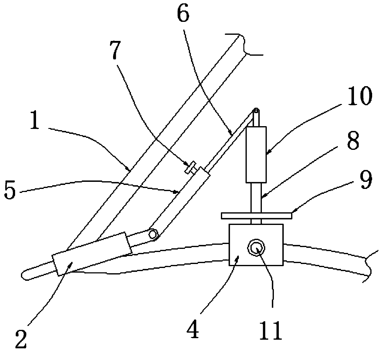
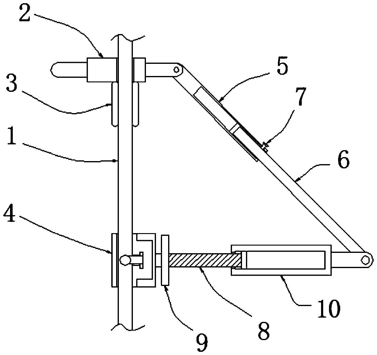
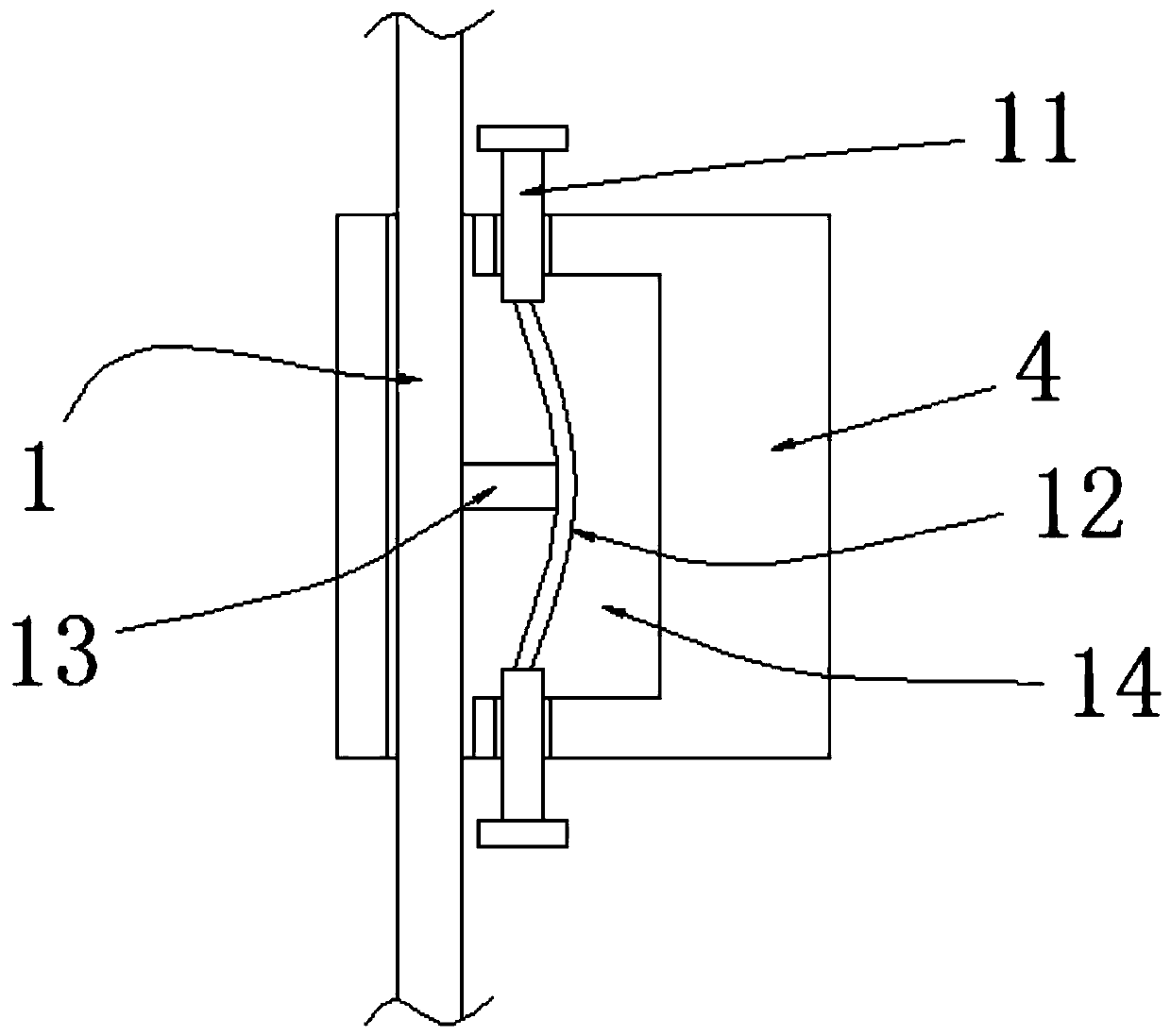
[0017] refer to Figure 1-3 , a car safety belt limit device, including a belt body 1, a clip joint 2 and a limit buckle 3, the limit buckle 3 is installed on the belt body 1, and the clip joint 2 is slidably installed on the belt body 1, and the clip The joint 2 is located above the limit button 3, and the tail of the clamp joint 2 is hinged with a telescopic adjustment device, and the end of the telescopic adjustment device is hinged with a sleeve 10, and the internal thread of the sleeve 10 is provided with a Threaded rod 8, and the end of the threaded rod 8 extends to the outside of the sleeve 10, the circumferential side wall of the threaded rod 8 is fixedly sleeved with a turntable 9, and the turntable 9 is located outside the sleeve 10 An adjustment block 4 is movably installed on the belt body 1, and one end of the threaded rod 8 located outside the sleeve 10 is rotatably connected to the side wall of the adjustment block 4, and the inside of the adjustment block 4 is provided with a mounting cavity 14, And the upper and lower ends of the adjustment block 4 are slidably installed with an adjustment rod 11, the end of the adjustment rod 11 extends to the inside of the installation cavity 14, the inside of the installation cavity 14 is provided with an elastic piece 12, and the elastic The upper and lower ends of the sheet 12 are respectively connected to one end of the two adjusting rods 11 that are close to each other, and the side of the elastic sheet 12 close to the belt body 1 is connected with a laterally arranged pressing rod 13, and the pressing rod The end of 13 is in contact with the belt body 1, the elastic sheet 12 is arranged in an arc-shaped structure, and the pressing rod 13 is arranged close to the inner wall of the elastic sheet 12, the end of the adjusting rod 11 is connected with a limit block, and the limit block is located at The external setting of the adjustment block 4, the telescopic adjustment device includes a first telescopic rod 5, a second telescopic rod 6 and a fastening screw 7, the inside of the first telescopic rod 5 is provided with a movable chamber, and the second telescopic rod 6 The end of the first telescopic rod 5 is movably installed in the inside of the movable chamber, and the circumferential side wall of the first telescopic rod 5 is threaded with a fastening screw 7, and the end of the fastening screw 7 extends to the inside of the movable chamber, and is connected with the second telescopic rod 5. The circumferential side walls of the rod 6 are in contact.
[0018] During the use of the car safety belt, first insert the clip joint 2 into the seat next to the car seat, then turn the fastening screw 7, so that the second telescopic rod 6 can slide inside the first telescopic rod 5, and then rotate turntable 9, and hold the sleeve 10, so that the turntable 9 drives the threaded rod 8 to rotate, and at the same time, the threaded rod 8 moves inside the sleeve 10, and the threaded rod 8 drives the adjustment block 4, so that the adjustment block 4 can pull the belt body 1, so that There is a distance between the belt body 1 and the abdomen of the passenger, so as to avoid excessive pressing force of the belt body 1 on the abdomen of the passenger. After the adjustment is completed, turn the fastening screw 7 in the opposite direction so that the fastening screw 7 is against the second telescopic rod 6 Fix the relative position of the second telescopic rod 6 and the first telescopic rod 5, and then fine-tune the position of the adjusting block 4 on the belt body 1. First, the two adjusting rods 11 can be squeezed so that the adjusting rod 11 Push the elastic sheet 12, and the elastic sheet 12 drives the pressing rod 13 to separate from the belt body 1. At this time, the position of the adjusting block 4 is fine-tuned. state, the elastic piece 12 pushes the adjusting rod 11 back to the initial state, and pushes the pressing rod 13 against the belt body 1 again, thereby completing the adjustment, which can make the distance between the belt body 1 and the abdomen of the passenger and limit it. bit.
[0019] The above is only a preferred embodiment of the present invention, but the scope of protection of the present invention is not limited thereto, any person familiar with the technical field within the technical scope disclosed in the present invention, according to the technical solution of the present invention Any equivalent replacement or change of the inventive concepts thereof shall fall within the protection scope of the present invention.

PUM

no PUM

Description & Claims & Application Information

We can also present the details of the Description, Claims and Application information to help users get a comprehensive understanding of the technical details of the patent, such as background art, summary of invention, brief description of drawings, description of embodiments, and other original content. On the other hand, users can also determine the specific scope of protection of the technology through the list of claims; as well as understand the changes in the life cycle of the technology with the presentation of the patent timeline. Login to view more.

Similar technology patents

Mechanical arm of educational robot

InactiveCN109093610AAvoid Excessive SqueezingNovel and reasonable structureProgramme-controlled manipulatorGripping headsEngineeringExtrusion
Owner:肇庆高新区异星科技有限公司

Freeze-dried food uniform dividing-twisting device

InactiveCN110813690AAvoid Excessive SqueezingImprove appearance integritySievingScreeningElectric machineryFreeze dry
Owner:耒阳市刘燕酿制生物科技有限公司

Vehicle following distance control method and device

InactiveCN111469840AThe solution is not smooth and continuousImprove ride comfortAutomotive engineeringSliding mode control
Owner:SAIC MOTOR

Classification and recommendation of technical efficacy words

  • Avoid Excessive Squeezing
  • Improve ride comfort

Mechanical arm of educational robot

InactiveCN109093610AAvoid Excessive SqueezingNovel and reasonable structureProgramme-controlled manipulatorGripping headsEngineeringExtrusion
Owner:肇庆高新区异星科技有限公司

Freeze-dried food uniform dividing-twisting device

InactiveCN110813690AAvoid Excessive SqueezingImprove appearance integritySievingScreeningElectric machineryFreeze dry
Owner:耒阳市刘燕酿制生物科技有限公司

Vibration reducer assembly and buffer block structure thereof

ActiveCN104864016AImprove ride comfortImproved ability to resist shock loadsElastic dampersShock absorbersBlock structureEngineering
Owner:GUANGZHOU AUTOMOBILE GROUP CO LTD
Why Eureka
Try Eureka