Antiskid lock of logistics transportation container

A locker and cargo box technology, applied in the field of logistics and transportation, can solve the problems of high installation cost, collision and damage of equipment or cargo boxes, property loss, etc., and achieve the effects of low cost, easy mass production, and safety assurance.

Active Publication Date: 2019-12-13
徐州鑫路达配送服务有限公司
View PDF7 Cites 1 Cited by
  • Summary
  • Abstract
  • Description
  • Claims
  • Application Information

AI Technical Summary

Problems solved by technology

[0002] The rise of the logistics industry in today's era has made the transfer between product equipment and goods more and more fast and efficient. However, at present, in the process of using large trucks to transport large equipment or containers, due to the fact that the trucks are transporting Due to the turbulence and inertial power generated in the truck compartment, the equipment or cargo boxes in the truck compartment are easily affected by the sliding offset, resulting in mutual collision and damage between the equipment or cargo boxes, resulting in damage to the equipment or cargo boxes, resulting in unnecessary property loss
[0003] Notification number CN208855508U discloses an anti-slip structure for automatic guided transport vehicle cargo transportation, including a base, fixed springs and rollers, the upper end surface of the base is laid with anti-skid bumps, and the edge of the top of the base is fixed with a storage box, and A telescopic cylinder is installed in the placement box, and one end of the telescopic cylinder is connected with a telescopic rod, and the telescopic rod is provided with a first clip, and a rubber pad is fixed on one side of the first clip, and the first clip The bottom is located in the movable groove, and the movable groove is opened on the base, the fixed spring is installed on one end of the side plate, and one end of the fixed spring is connected with a second clamping plate, and the roller is fixed on the outside of the side plate. There is a bottom groove reserved on the top of the base, and the other end of the nylon rope is connected to the bearing plate. This anti-slip device can only be used on a fixed transport vehicle, and at the same time, the installation cost is relatively high, and free and portable movement cannot be carried out use
[0004] The notification number CN106335727A discloses a locking device for stabilizing logistics container storage. The bottom of the container storage tank is provided with a locking loading part that is fixedly connected to the logistics shelf and has a hollow cavity inside. The rear of the logistics container The end face is integrally provided with two bendable locking arms symmetrically distributed on the left and right. The two bendable locking arms are used to be inserted into the hollow cavity of the locking loading part through elastic deformation. The front end of the locking loading part Elastic parts are provided on the surface to play a buffer role when the two bendable locking arms are inserted into the hollow cavity of the locking loading part through elastic deformation. This device is inconvenient to install and use, and cannot be used for portable movement

Method used


Image

  • Antiskid lock of logistics transportation container
  • Antiskid lock of logistics transportation container
  • Antiskid lock of logistics transportation container

Examples


Embodiment 1

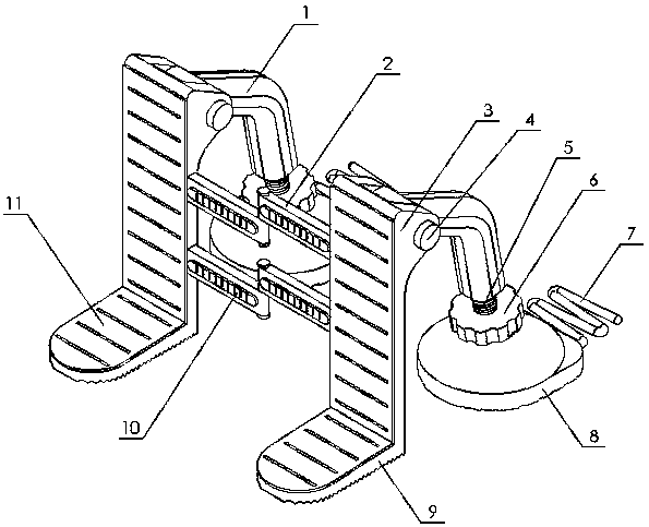
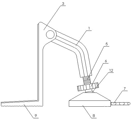
[0025] An anti-slip locker for a logistics transport container of the present invention is realized in this way. The anti-slip locker for a logistics transport container of the present invention is composed of two supporting parts that can deflect relative to each other, and two sets of connecting rods ( 2) Hinged, the supporting part is composed of a supporting bent rod (1), a supporting plate (3), a connecting shaft (4), a screw rod (5), a screw cap (6), a bending piece (7), and a base (8) , an insert plate (9), a gasket (10), a wear-resistant pad (11) and a spherical joint (12), and one end of the support bending rod (1) is hinged to one end of the support plate (3) through a connecting shaft (4). The insertion plate (9) is placed on the other end of the support plate (3), the angle between the insertion plate (9) and the support plate (3) is 95°-100°, the support bending rod (1) and the insertion plate ( 9) Located on both sides of the supporting plate (3), the bending ang...

Embodiment 2

[0032] The difference between embodiment 2 and embodiment 1 is that the connection between the two supporting parts is connected by the auxiliary rod, and the two ends of the auxiliary rod are respectively hinged with the connecting rod (2), which can be further used for the transportation of machine tool equipment. Special-shaped corners are attached to the protective support to improve the stability of the support, and the auxiliary rod can increase the angle adjustment range between the two support parts;

Embodiment 3

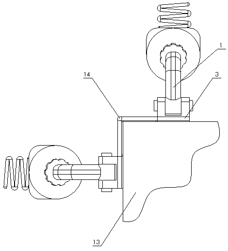
[0034] The difference between Embodiment 3 and Embodiment 1 is that only one of the two support parts is provided with a support rod, and a foldable and accommodated support arm is added at the hinge shaft (14) of the connecting rod (2), and the support arm is composed of It is composed of a sleeve rod for storage and a support foot hinged to the end of the sleeve rod for support. The sleeve rod is fixed by the hinge shaft (14). Embodiment 3 is targeted at different weight distributions of the equipment to be fixed. The position of the support point saves space and provides auxiliary support;


PUM


Abstract

The invention discloses an antiskid lock of a logistics transportation container, and discloses a fixing device which is used for gravity decomposing through the dead weight of cargoes or equipment, used for lateral supporting and meanwhile used for supporting and fixing in cooperation with a triangular stable supporting structure to prevent the cargoes or equipment from shifting and expanding. The antiskid lock is characterized by being composed of two supporting parts capable of relatively deflecting, the two supporting parts are hinged through two connecting rods, each supporting part is composed of a supporting bent rod, a supporting plate, a connecting shaft, a screw, a rotary cap, a bent piece, a base, an insertion plate, a spacer, a wear-resistant cushion and a spherical joint, oneend of each supporting bent rod is hinged to one end of the corresponding supporting plate through the corresponding connecting shaft, each insertion plate is placed at the other end of the corresponding supporting plate, the included angle between each insertion plate and the corresponding supporting plate is 95-100 degrees, each supporting bent rod and the corresponding insertion plate are located on the two sides of the corresponding supporting plate correspondingly, and the bent angle of each supporting bent rod is 120-150 degrees.

Description

technical field [0001] The invention relates to an anti-slip locker for a logistics transportation container, which relates to a fixing device for supporting and stabilizing special-shaped corners of the container or equipment during transportation, and belongs to the field of logistics transportation. In particular, it relates to a fixing device that uses the self-weight of goods or equipment to decompose by gravity, and is used for lateral support, and is supported and fixed in combination with a triangular stable support structure to prevent offset expansion between goods or settings. Background technique [0002] The rise of the logistics industry in today's era has made the transfer between product equipment and goods more and more fast and efficient. However, at present, in the process of using large trucks to transport large equipment or containers, due to the fact that the trucks are transporting Due to the turbulence and inertial power generated in the truck compart...

Claims


Application Information

Patent Timeline
IPC IPC(8): B65D90/12
CPCB65D90/12
Inventor 不公告发明人
Owner 徐州鑫路达配送服务有限公司
Why Eureka
Try Eureka