Solar photovoltaic wall panel
A solar photovoltaic and wall panel technology, applied in the field of solar photovoltaic panels, can solve the problems of occupying farmland, occupying a large space, and hidden dangers of safety, etc., and achieve the effect of increasing the annual radiation amount, increasing the direct radiation ratio, and broadening the application space and scope
- Summary
- Abstract
- Description
- Claims
- Application Information
AI Technical Summary
Problems solved by technology
Method used
Image

Examples
Embodiment Construction
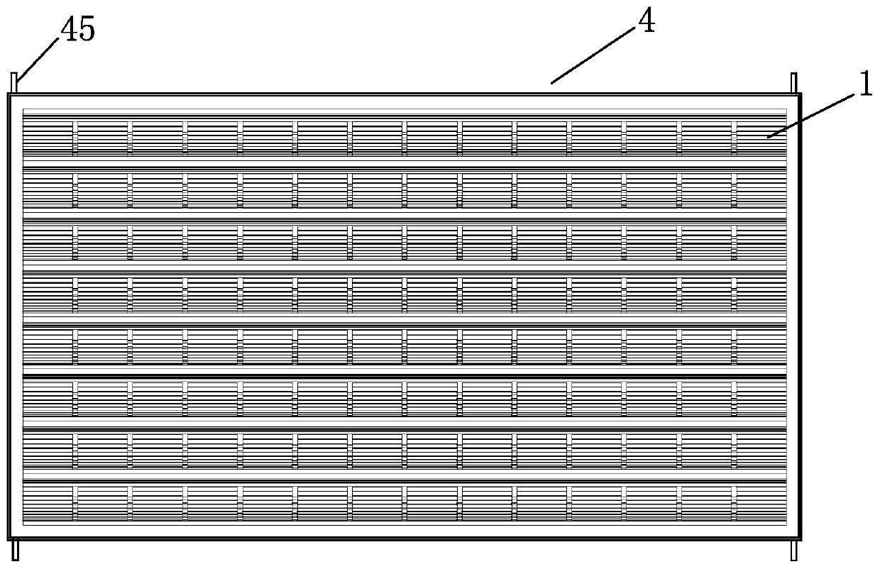
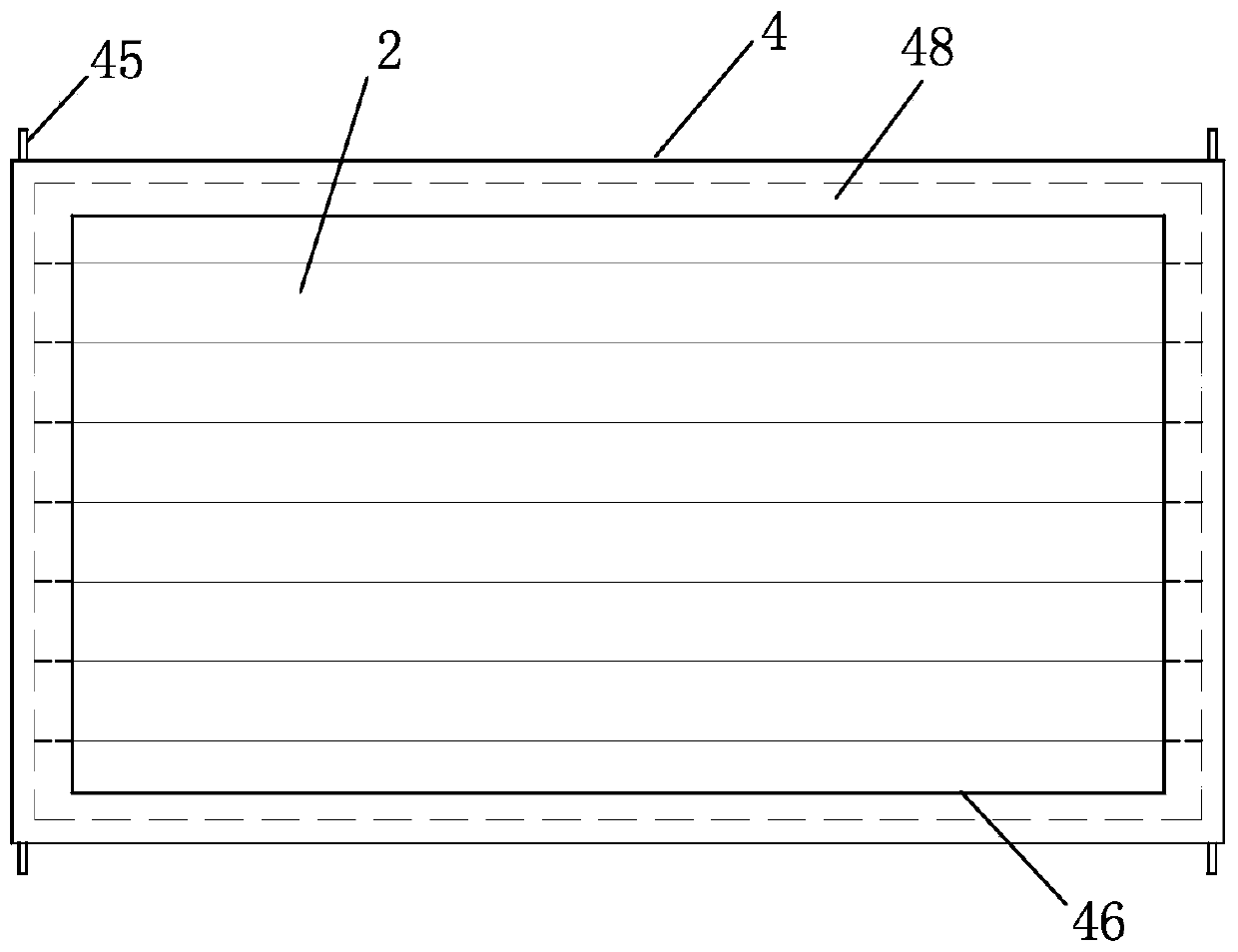
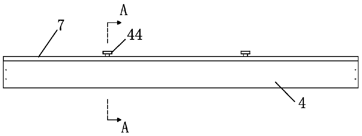
[0039] Such as figure 1 , image 3 and Figure 4 As shown, a solar photovoltaic wall panel includes a front and rear frame 4 and a back frame 7 that are attached to each other. Both the frame 4 and the back frame 7 are hollow and rectangular. Such as figure 2 and Figure 5 As shown, the back side of the frame 4 forms an inner flange 48 . Such as figure 2 As shown, eight brackets 2 are arranged in sequence from top to bottom in the frame 4 . The back of the bracket 2 is glued together with the inner flange 48 of the frame 4 , and the left and right end surfaces of the bracket 2 are glued together with the inner side 49 of the frame 4 . Such as Figure 7 As shown, the upper surface of the uppermost bracket 2 is bonded to the inner upper surface 410 of the frame 4 , and the lower surface of the lowermost bracket 2 is bonded to the inner lower surface 411 of the frame 4 . The upper and lower surfaces of two adjacent brackets 2 are glued together.
[0040] Such as figu...
PUM
| Property | Measurement | Unit |
|---|---|---|
| Radius | aaaaa | aaaaa |
| Thickness | aaaaa | aaaaa |
| Length | aaaaa | aaaaa |
Abstract
Description
Claims
Application Information