
Plasma display device and driving method thereof

A technology of a display device and a display method, which is applied in the directions of identification devices, static indicators, instruments, etc., can solve the problems of inability to improve the contrast between light and dark, inability to improve brightness, and difficulty in displaying the color of a plasma display panel.

Inactive Publication Date: 2008-12-03
LG ELECTRONICS(NANJING) PLASMA CO LTD
View PDF5 Cites 0 Cited by
  • Summary
  • Abstract
  • Description
  • Claims
  • Application Information

AI Technical Summary

Problems solved by technology

[0011] Therefore, the ratio of the brightness of the brightest white peak peak white in the picture displayed on the above-mentioned plasma display panel to the dark brightness without discharge, that is, the contrast ratio (Contrast) cannot be improved.
[0012] That is, the luminance of the peak white display portion is mainly determined by the light generated when the sustain signal (S) is input, and the dark luminance is determined by the initial discharge caused by the input of the initial signal (R). The initial discharge at the initial signal will produce weak light, resulting in the inability to improve the contrast between light and dark
[0013] At the same time, due to the light generated by the above-mentioned initial discharge, the display of the relatively dark part is abnormal, so it is difficult to display the correct color on the plasma display panel.

Method used


Image

  • Plasma display device and driving method thereof
  • Plasma display device and driving method thereof
  • Plasma display device and driving method thereof

Examples


Embodiment Construction

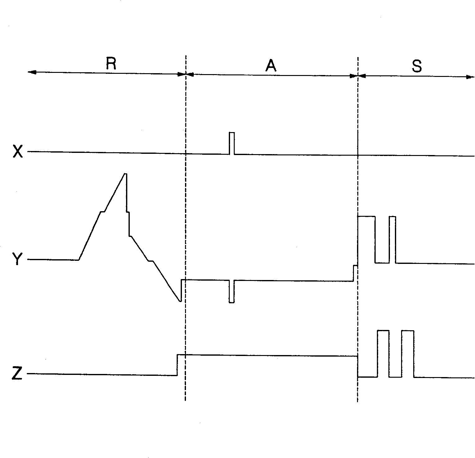
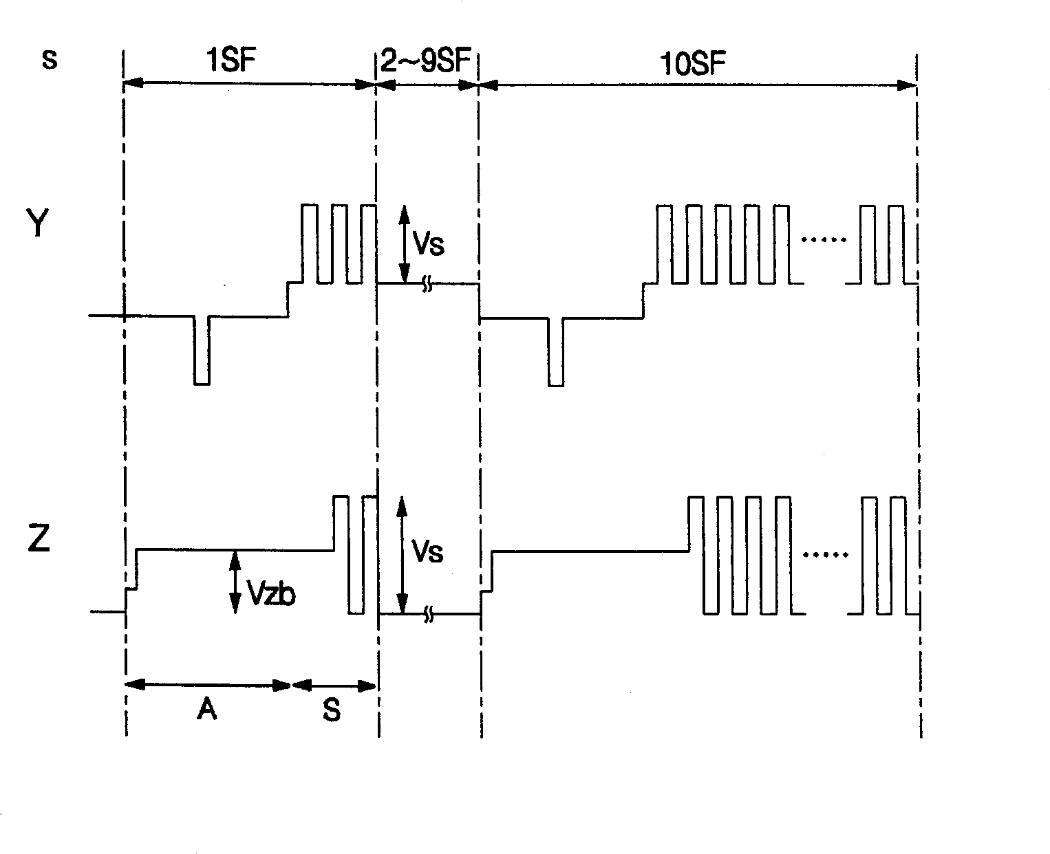
[0027] Hereinafter, a plasma display device according to the present invention will be described with reference to the drawings. Figures 3a to 3b is a diagram illustrating driving waveforms of a plasma display panel in the present invention, Figures 4a to 4b It is a diagram showing an example of an initialization waveform input to a plasma display panel in the present invention.

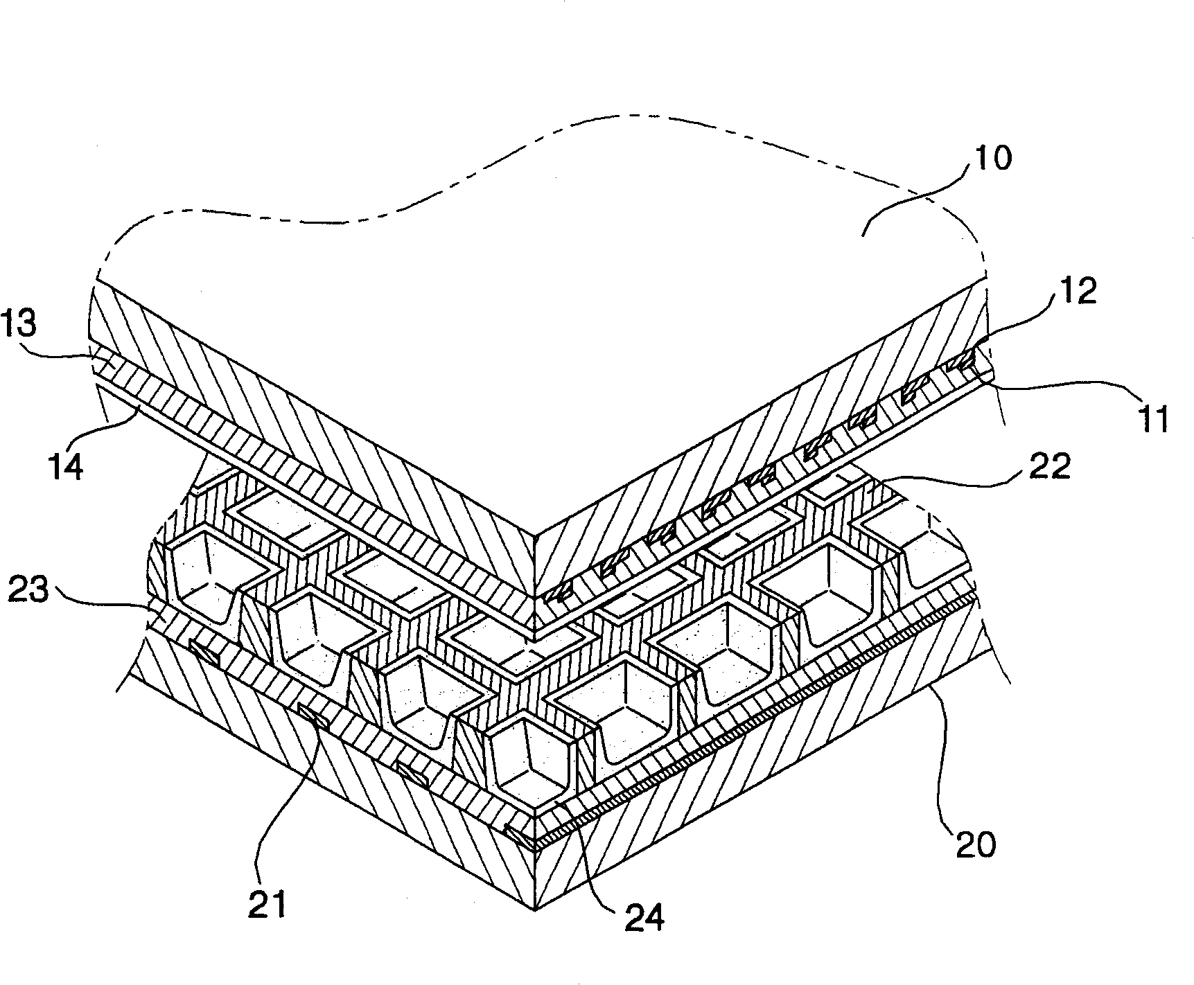
[0028] In the present invention, the plasma display panel has a module composed of a plurality of address electrodes (X) arranged in the column direction, and a plurality of scan electrodes (Y) and sustain electrodes (Z) arranged in the horizontal direction. The scan electrodes correspond to the sustain electrodes, and one ends of the sustain electrodes are connected to each other and transmit the same voltage.

[0029] The module is formed by combining the front panel formed by the scan electrodes (Y) and the sustain electrodes (Z) alternately horizontally and the rear panel formed by the address...


PUM


Abstract

A plasma display device and a driving method thereof are provided to improve contrast by increasing the maximum luminance and controlling the minimum luminance by applying only an address signal and a sustain signal without a reset signal when a still image is displayed. A plasma display device has a driving unit for applying driving waveform comprising an address signal(A) and a sustain signal(S) when a still image is displayed. The driving waveform includes a setdown reset signal(R_dn). The driving unit applies bias voltage to a sustain electrode(Z) while the address signal is applied to a scan electrode(Y). The driving unit applies sustain pulse to the sustain electrode and the scan electrode in turn while the sustain signal is applied to the scan electrode.

Description

technical field [0001] The present invention relates to a plasma display device and a driving method thereof, in particular to a plasma display panel that only inputs an addressing signal and a sustain signal when displaying a stop image signal, thereby preventing an increase in dark brightness caused by initial discharge and improving the light-dark ratio A plasma display device and a driving method thereof. Background technique [0002] figure 1 It is a structural diagram of an existing plasma display panel. [0003] The plasma display panel is a display device that uses vacuum ultraviolet rays (VUV) generated during gas discharge inside the panel to excite fluorescent agents inside the panel to generate light, and is roughly formed by a front substrate (10) and a back substrate (20). [0004] The structure of a general plasma display panel is as follows: figure 1 As shown, the front panel substrate (10) is composed of a plurality of scan electrodes (11) of a stripe-sha...

Claims


Application Information

Patent Timeline
Patent Type & Authority Patents(China)
IPC IPC(8): G09G3/28G09G3/20H01J17/49G09F9/313G09G3/296G09G3/291
CPCG09G3/291G09G3/294G09G3/296
Inventor 金元在李城任都鉉洛
Owner LG ELECTRONICS(NANJING) PLASMA CO LTD
Features
  • Generate Ideas
  • Intellectual Property
  • Life Sciences
  • Materials
  • Tech Scout
  • Unparalleled Data Quality
  • Higher Quality Content
  • 60% Fewer Hallucinations
Learn More