
Vibration isolation roofing equipment foundation construction

A technology for equipment foundation and structure, applied in basic structure engineering, roofing, building construction, etc., can solve the problems of increasing construction costs, increasing the shielding components of roof equipment, affecting the rational use of building height, etc., to achieve good roof integrity, Effort and time savings, the effect of reducing the extent of the cold bridge

Inactive Publication Date: 2019-12-13
SHANGHAI ARCHITECTURAL DESIGN & RES INST
View PDF0 Cites 5 Cited by
  • Summary
  • Abstract
  • Description
  • Claims
  • Application Information

AI Technical Summary

Problems solved by technology

According to the building height calculation requirements of the relevant regulations, the ancillary facilities with a height of more than 6 meters on the roof need to be included in the building height, and the above-mentioned cooling tower is an ancillary facility, which directly affects the rational use of the building height. It is necessary to add additional shielding components to shield the roof equipment, which will not only increase the construction cost, but also have a greater impact on the height and function of each floor building

Method used


Image

  • Vibration isolation roofing equipment foundation construction
  • Vibration isolation roofing equipment foundation construction
  • Vibration isolation roofing equipment foundation construction

Examples


Embodiment Construction

[0023] The specific implementation manners of the present invention will be described in further detail below in conjunction with the accompanying drawings. These embodiments are only used to illustrate the present invention, not to limit the present invention.

[0024] In the description of the present invention, it should be noted that the terms "center", "longitudinal", "transverse", "upper", "lower", "front", "rear", "left", "right", " The orientations or positional relationships indicated by "vertical", "horizontal", "top", "bottom", "inner" and "outer" are based on the orientations or positional relationships shown in the drawings, and are only for the convenience of describing the present invention and Simplified descriptions, rather than indicating or implying that the device or element referred to must have a particular orientation, be constructed and operate in a particular orientation, and thus should not be construed as limiting the invention. In addition, the ter...


PUM


Abstract

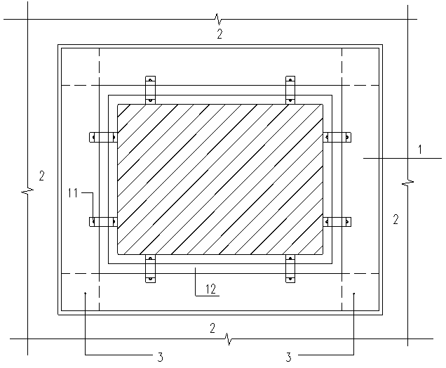
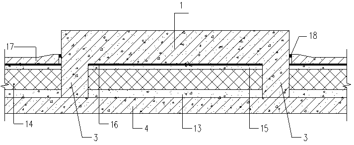
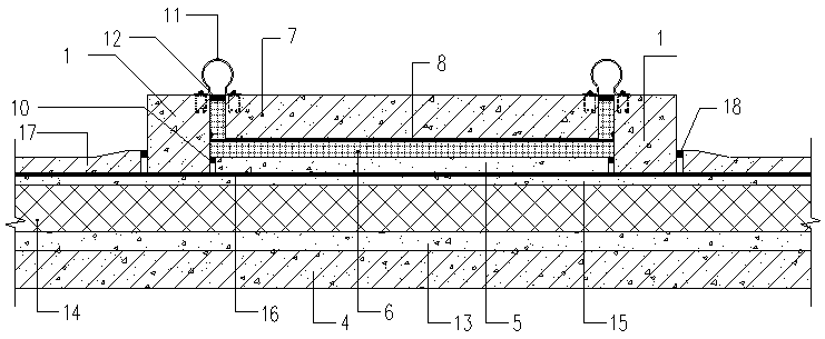
The invention belongs to a vibration isolation roofing equipment foundation construction in the field of construction engineering vibration isolation. According to the technical scheme, a concrete constructional frame is placed flat on a roofing waterproof insulation layer, constructional columns are arranged at the corners of the concrete constructional frame, and column feet of the constructional columns are fixedly connected with a structural layer; a protective layer, an elastic cushion layer, a waterproof layer and a concrete slab floating building layer are successively laid from bottomto top on the space in the concrete constructional frame; and a connecting ring is arranged at the frame edge of the concrete constructional frame, one end of the connecting ring is connected with theframe edge, the other end of the connecting ring is connected with the top surface of the concrete slab floating building layer, and the finished surface is laid on the roofing waterproof insulationlayer outside the concrete constructional frame. According to the vibration isolation roofing equipment foundation construction, the problem of vibration isolation and waterproofing of a roofing equipment foundation is conveniently solved, building cold bridge formation is reduced, the effect of solid sound transmission on the building space under a roofing is lowered, the purposes of environmental protection and energy saving are achieved, and meanwhile, reasonable control and layout the heights and planes of buildings by architects are convenient.

Description

technical field [0001] The invention belongs to the field of construction engineering vibration isolation, in particular to a vibration isolation structure of a roof equipment foundation. Background technique [0002] There are usually some electromechanical equipment with continuous vibration or low-frequency noise installed on the roof of the building. Buildings of different types and sizes have different types and quantities of equipment. In recent years, vibration and sound insulation materials, including spring dampers, rubber damping pads, and composite dampers made of rubber and spring dampers have begun to be widely used. The engineering method is based on civil engineering on the installation and construction. However, there are limited options for vibration isolation materials, high cost, and damage to the roof construction system. [0003] Generally, the basic installation of roof equipment is done directly on the roof structure layer after the roof structure la...

Claims


Application Information

Patent Timeline
IPC IPC(8): E04D13/14E04D13/16E02D27/44E02D27/32
CPCE02D27/32E02D27/44E04D13/1407E04D13/1687
Inventor 陈国亮潘嘉凝周涛朱磊鑫姚军苏骏
Owner SHANGHAI ARCHITECTURAL DESIGN & RES INST
Learn More