
Centralized water supply and intelligent hot water discharge device and control method thereof

A technology of a hot water device and a control method, which is applied in the field of hot water supply equipment, can solve the problems affecting the use of users, long pipelines, low water pressure at the user end, etc., and achieve the effect of good thermal insulation effect.

Active Publication Date: 2019-12-13
YANGZHOU HANJIANG SYT ELECTRONICS & TECH DEV CENT
View PDF9 Cites 1 Cited by
  • Summary
  • Abstract
  • Description
  • Claims
  • Application Information

AI Technical Summary

Problems solved by technology

Its disadvantages are: 1. During the heat preservation cycle, the booster pump is turned on. In order to meet the requirements of simultaneous use by the user group, the power and displacement of the booster pump are generally relatively large. The heat preservation cycle is carried out by using the booster pump. High energy consumption
2. The device fails to solve the problem of how to solve the user's water consumption when the circulating solenoid valve is turned on. If the user turns on the faucet when the circulating solenoid valve is turned on, and uses a large amount of water, only a small amount of return water may pass through the temperature sensor, and the circulating solenoid valve is more expensive. Keeping it open for a long time makes the water pressure at the user end low, which affects the user's use
3. This device is not suitable for central heating. When it is used for central heating, it has the following characteristics: a. When it is used at low peak, only a very small number of users are using it, and the water flow is small; The water flow rate is relatively large; the b pipeline is long, and the drop of the water point may be relatively large
If a large flow circulation pump is used all the time, the energy consumption will be higher

Method used


Image

  • Centralized water supply and intelligent hot water discharge device and control method thereof

Examples


Embodiment Construction

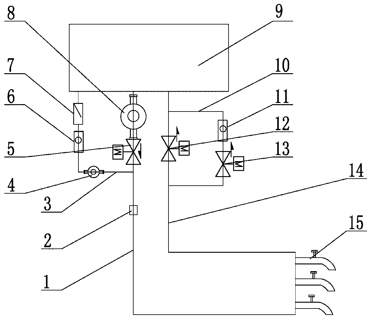
[0029] Such as figure 1As shown, a centralized water supply intelligent hot water outlet device includes a high-level water storage tank 9, a main water pump 8, a water outlet solenoid valve 5, a high temperature sensor 2, a return water solenoid valve, and a hot water valve 15. The main water pump 8 1. The water outlet solenoid valve 5 is arranged on the water outlet pipeline 1, and the return water solenoid valve is arranged on the return water pipeline 14. The outlet water pipeline 1 and the return water pipeline 14 are arranged with equal diameters. One end is respectively connected to the water storage tank 9, the other end of the outlet pipe 1 and the return pipe 14 are connected to each other, the hot water valve 15 is bypassed between the outlet pipe 1 and the return pipe 14, and the high temperature sensor 2 is set on the outlet pipe 1, the water outlet pipeline 1 is also connected with a water outlet branch pipe 3, and the water outlet branch pipe 3 is provided with ...


PUM


Abstract

The invention relates to a centralized water supply and intelligent hot water discharge device and a control method thereof in the technical field of hot water supply equipment. The device comprises awater storage tank arranged in a higher place; a main water pump and a water outlet electromagnetic valve are arranged on a water outlet pipeline; a water return electromagnetic valve is arranged ona water return pipeline; the water outlet pipeline is connected with a water outlet branch pipe; a micro water pump, a water outlet water flow sensor and a one-way valve are arranged on the water outlet branch pipe; an inlet end of the one-way valve is connected with the water storage tank; a water return branch pipe is arranged on the water return pipeline; a water return water flow sensor and awater return branch pipe electromagnetic valve are arranged on a pipeline of the water return branch pipe; the two ends of the water return branch pipe are bridged and connected to the two ends of thewater return electromagnetic valve; and the effective through-flow cross sectional area of the water outlet branch pipe is 5-20% of the effective through-flow cross sectional area of the water outletpipeline. The device can insulate the pipes under the condition of low energy consumption, and can quickly switch an insulation state and a water use state.

Description

technical field [0001] The invention relates to the technical field of hot water supply equipment, in particular to a centralized hot water supply device. Background technique [0002] Solar water heaters, air energy water heaters, and gas water heaters are centrally installed on the roofs or roofs of enterprises, hotels or hospitals, and one or more large water tanks supply hot water to each hot water point or room. Point or room hot water outlet valve or the front branch pipe of the hot water outlet valve is connected, because there is always water in the pipe, and the water will not heat up. Constant temperature circulation or constant temperature circulation + timing circulation are commonly used in the industry. The circulation path is: water storage tank-outlet pipe-return water pipe-water storage tank, which can solve the problem of hot water in the main pipe of the water outlet pipe becoming cold. For example: a double-tube instant-on solar water heater is disclosed...

Claims


Application Information

Patent Timeline
Patent Type & Authority Applications(China)
IPC IPC(8): F24D17/00F24D19/10
CPCF24D17/0078F24D19/1051
Inventor 朱开云朱晓俊朱领军
Owner YANGZHOU HANJIANG SYT ELECTRONICS & TECH DEV CENT
Learn More