
Nondestructive testing method and device for steel wire rope

A non-destructive testing and steel wire rope technology, applied in the field of steel wire rope testing, can solve the problems of low detection accuracy, inability to quantitatively detect cross-sectional loss, complex calculations, etc.

Active Publication Date: 2019-12-13
HARBIN INST OF TECH SHENZHEN GRADUATE SCHOOL
View PDF6 Cites 7 Cited by
  • Summary
  • Abstract
  • Description
  • Claims
  • Application Information

AI Technical Summary

Problems solved by technology

However, for defects with a large axial width, the information of the defects cannot be accurately identified, and the amount of cross-section loss cannot be quantitatively detected, so complex calculation methods such as neural networks are needed for quantitative analysis.
This method can only identify surface defects, not internal defects
This method needs to do a lot of standard defects to train a specific artificial neural network for classification and recognition. If you change the type of wire rope, you need to retrain the artificial neural network
[0005] Therefore, the current electromagnetic detection method cannot quantitatively detect the section loss of all defects in the steel wire rope, and the detection accuracy is very low and the calculation is complicated

Method used


Image

  • Nondestructive testing method and device for steel wire rope
  • Nondestructive testing method and device for steel wire rope
  • Nondestructive testing method and device for steel wire rope

Examples


Embodiment Construction

[0076] It should be understood that the specific embodiments described here are only used to explain the present invention, not to limit the present invention.

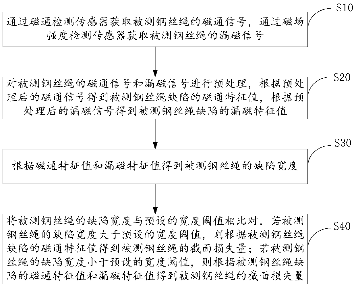
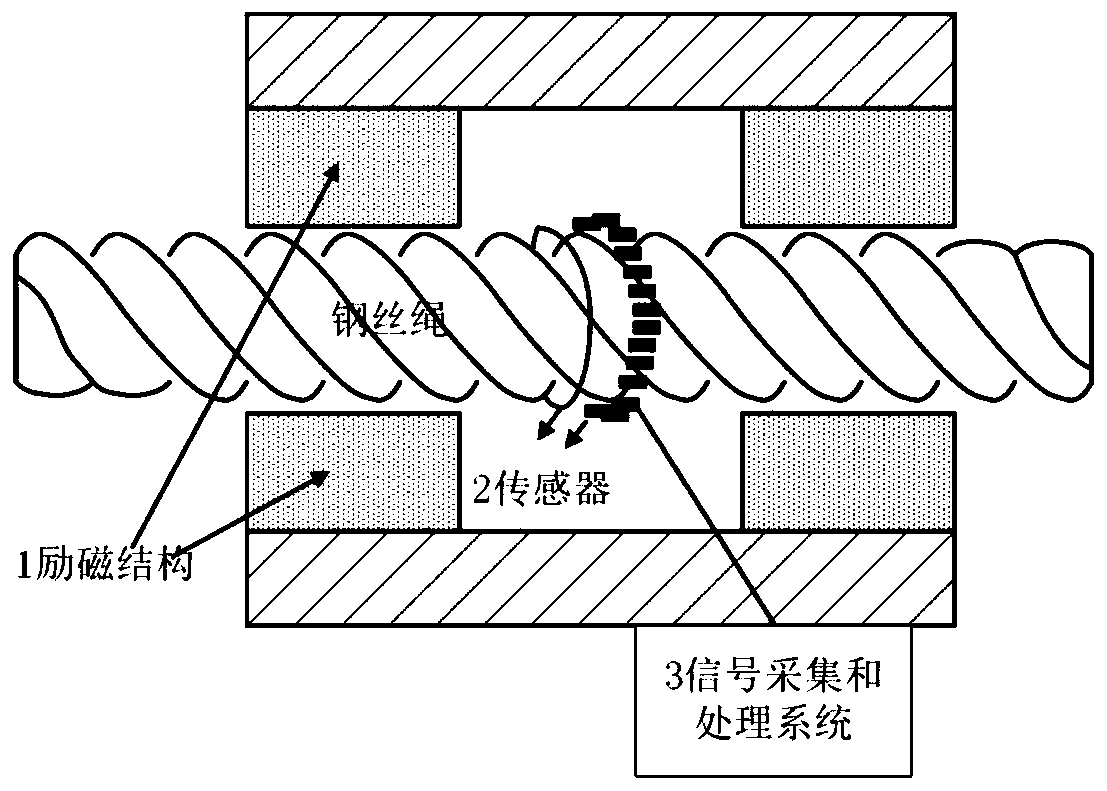
[0077] Considering that the current electromagnetic detection method cannot quantitatively detect the cross-sectional loss of all defects of the steel wire rope, and the detection accuracy is very low, and the calculation is complicated. Therefore, the present invention proposes a method and device for non-destructive detection of steel wire ropes by detecting magnetic flux and magnetic field leakage. , the present invention can not only identify all defect types including internal defects of the tested steel wire rope by detecting the magnetic flux and leakage field, but also has the advantages of high quantitative accuracy of section loss and simple calculation.

[0078] Specifically, please refer to figure 1 , figure 1 It is a schematic flow chart of a preferred embodiment of the non-destructive testing method for...


PUM


Abstract

The invention provides a nondestructive testing method and device for a steel wire rope. The method comprises a step of obtaining a magnetic flux signal of a detected steel wire rope through a magnetic flux detection sensor and obtaining a magnetic flux leakage signal of the detected steel wire rope through a magnetic field intensity detection sensor, a step of preprocessing the magnetic flux signal and the magnetic flux leakage signal, obtaining a magnetic flux characteristic value according to the preprocessed magnetic flux signal, and obtaining a magnetic flux leakage characteristic value according to the preprocessed magnetic flux leakage signal, a step of obtaining a defect width of the detected steel wire rope according to the magnetic flux characteristic value and the magnetic fluxleakage characteristic value, a step of comparing the defect width of the detected steel wire rope with a preset width threshold value, a step of obtaining a section loss amount of the detected steelwire rope according to the magnetic flux characteristic value if the defect width is larger than or equal to the preset width threshold value, and a step of obtaining the section loss of the detectedsteel wire rope according to the magnetic flux characteristic value and the magnetic flux leakage characteristic value if the defect width is smaller than the preset width threshold value. All types of defects of the detected steel wire rope can be identified, and the section loss quantitative precision is high.

Description

technical field [0001] The invention belongs to the technical field of steel wire rope detection, and in particular relates to a method and device for non-destructive detection of steel wire ropes by detecting magnetic flux and magnetic field leakage. Background technique [0002] Wire ropes are widely used in industrial, civil, military and other fields. With the use of time, various damages to the wire rope are inevitable, which will significantly reduce the mechanical properties of the material such as strength, toughness, and plasticity, and seriously affect its safe use, so regular inspections are required. Among them, the section loss of steel wire rope defects directly affects the quality of steel wire ropes, so the quantitative detection of section loss of steel wire rope defects is the most important. [0003] Electromagnetic detection method is the most commonly used effective method, which includes two conditions of saturated excitation and non-saturated excitati...

Claims


Application Information

Patent Timeline
Patent Type & Authority Applications(China)
IPC IPC(8): G01N27/82G01N27/83G01B7/02
CPCG01N27/82G01N27/83G01B7/02
Inventor 张东来张恩超潘世旻晏小兰高伟
Owner HARBIN INST OF TECH SHENZHEN GRADUATE SCHOOL
Learn More