
High-power transmitting device for radio wave scenograph

A radio wave perspective and transmitting device technology, applied in the field of radio waves, can solve the problems of low transmission power of a single unit, limited system application environment, and high cost, and achieve the advantages of improving the strength of the space magnetic field, improving the adaptive ability, and increasing the detection ability. Effect

Pending Publication Date: 2019-12-13
FUZHOU HUAHONG INTELLIGENT TECH
View PDF0 Cites 0 Cited by
  • Summary
  • Abstract
  • Description
  • Claims
  • Application Information

AI Technical Summary

Problems solved by technology

However, the transmission power of the radio wave perspective instrument used in underground mines is limited by safety regulations, and the output power of a single transmitter is less than 6W, so some large and wide working faces cannot penetrate
At present, it is proposed to use two transmitters to achieve the purpose of transmitting together by adjusting the phase of the sine wave through synchronization, but this design has the following defects: 1. The transmission power of a single transmitter is small, and the signal cannot pass through the working surface with a large surface width. The application environment of the system is limited; 2. Two transmitters are used to realize synchronous transmission through the synchronous sine wave phase mode. To realize this function, the system design is complicated and the cost is high; 3. When the power of the two transmitters cannot meet the detection requirements, Unable to achieve multiple cascaded parallel launches

Method used


Image

  • High-power transmitting device for radio wave scenograph
  • High-power transmitting device for radio wave scenograph
  • High-power transmitting device for radio wave scenograph

Examples


Embodiment 1

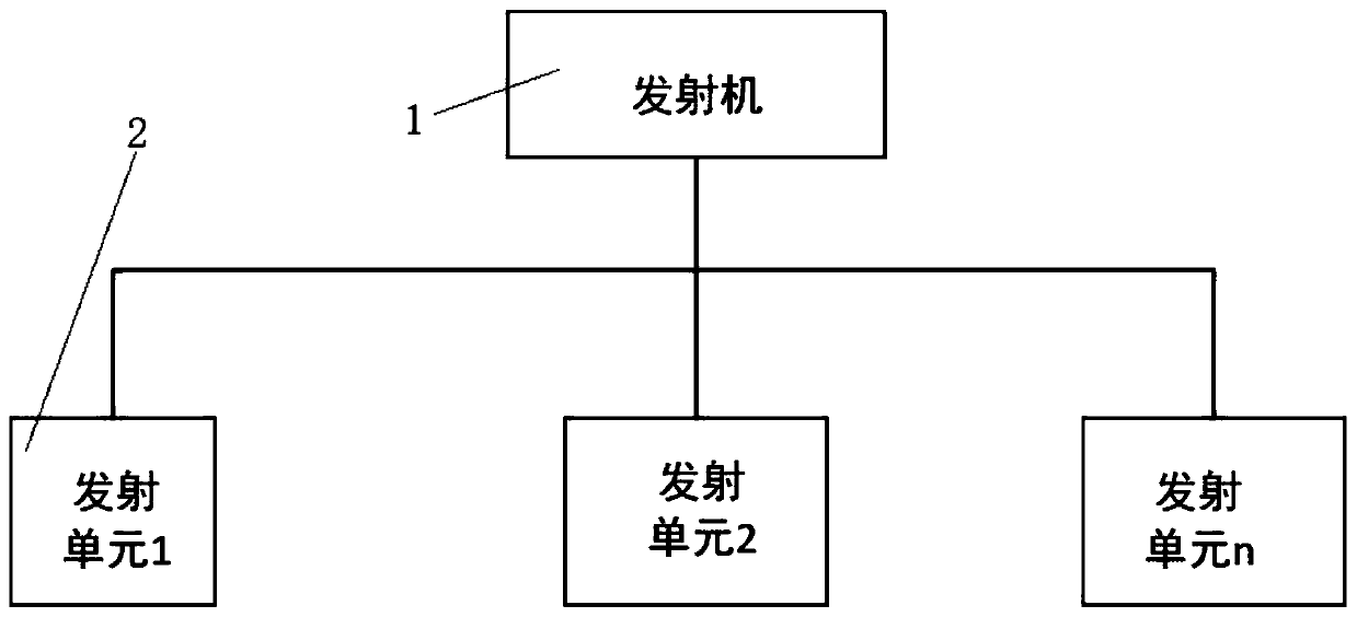
[0018] Example 1: Please refer to Figure 1-3 , the present invention provides a technical solution: a high-power radio wave perspective instrument transmitting device, including a transmitter 1 and a transmitting unit 2, there are several transmitting units 2, and the transmitting unit 2 is connected to the transmitter 1 through a cable;

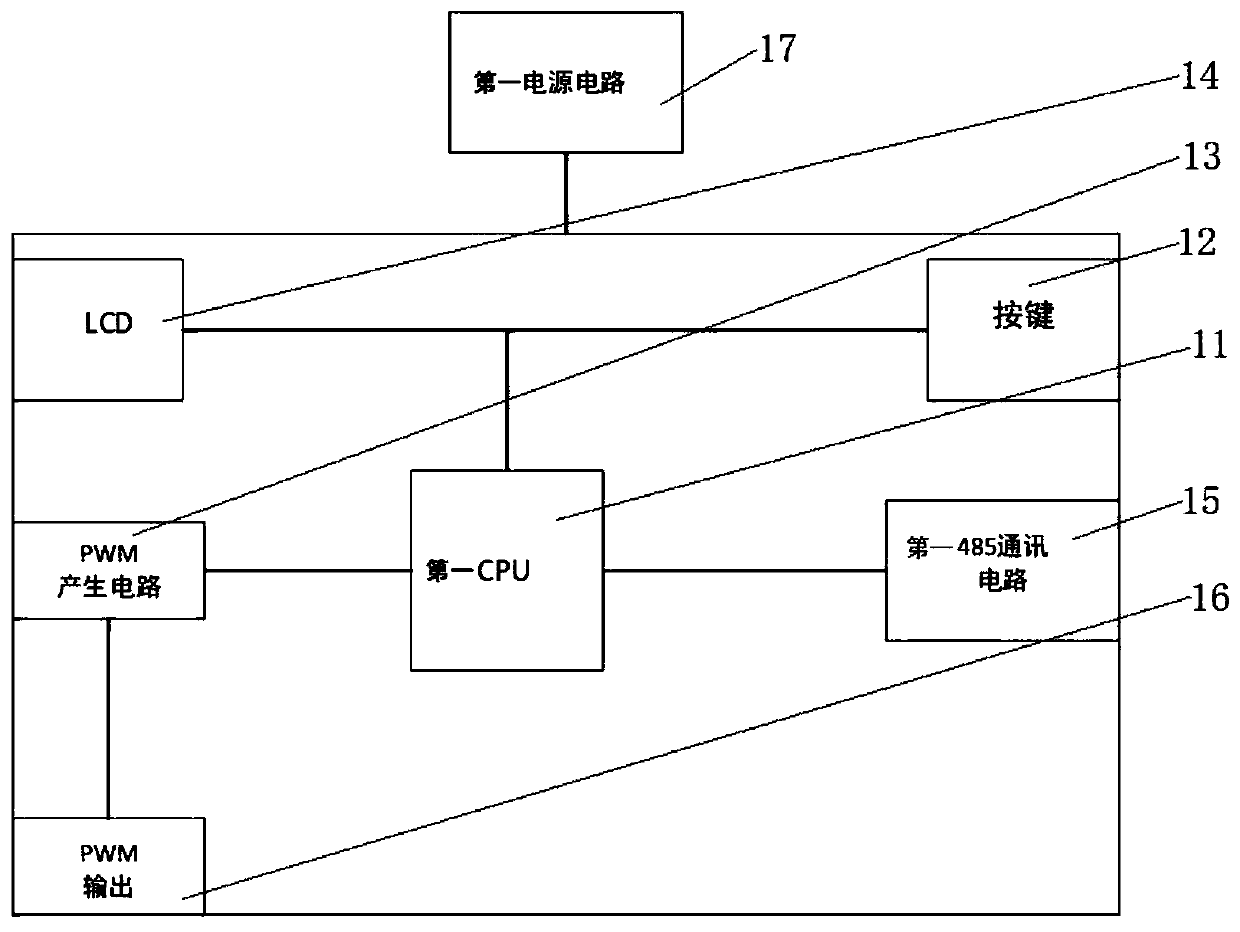
[0019] Described transmitter 1 comprises first CPU11, button 12, PWM generation circuit 13, LCD14, first 485 communication 15, PWM output 16 and first power supply circuit 17, first CPU11 of first power supply circuit 17, button 12, PWM generation Circuit 13, LCD14, first 485 communication 15 and PWM output are connected with 16, the first CPU11 is connected with PWM output 16 through PWM generating circuit 13, button 12 is connected with LCD14, first CPU11 is connected with button 12 and LCD14, first CPU11 Connect with the first 485 communication 15;

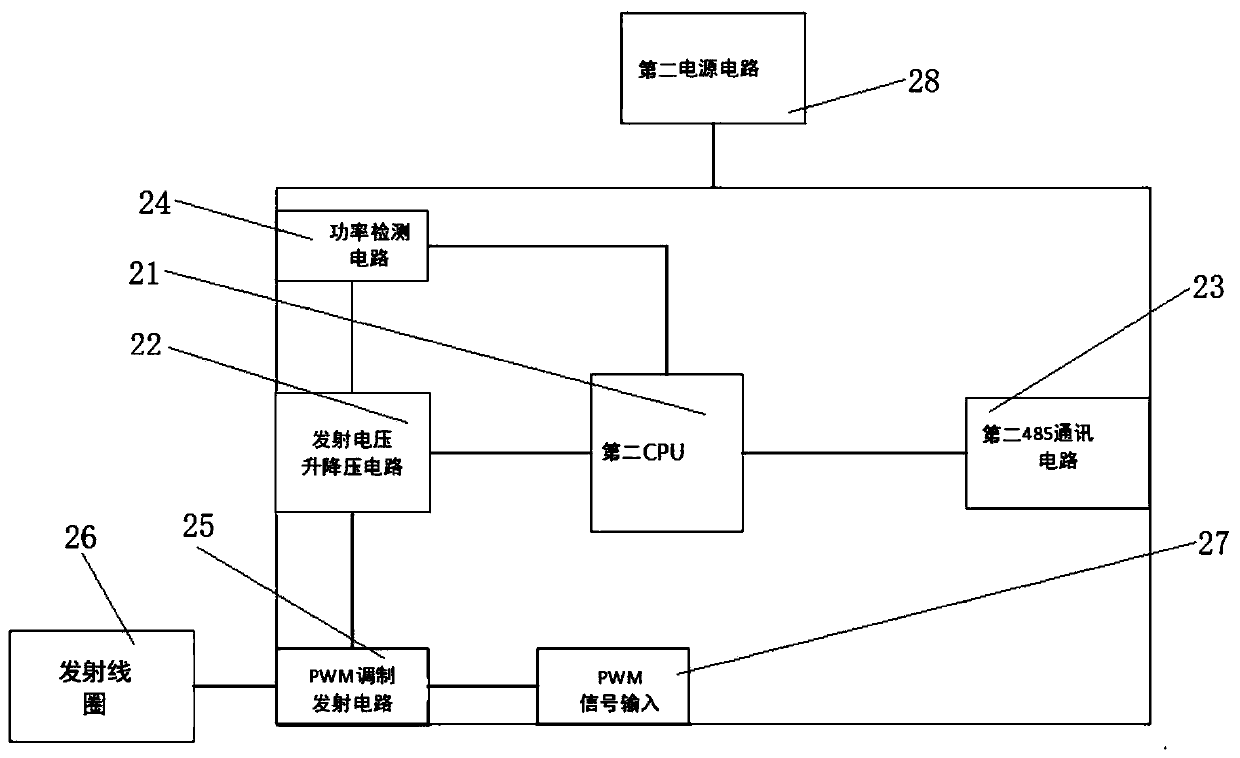
[0020] The transmitting unit 2 includes a second CPU 21, a transmitting voltage step-do...


PUM


Abstract

The invention discloses a high-power transmitting device for a radio wave scenograph. The high-power transmitting device comprises a transmitter and transmitting units; a plurality of transmitting units are arranged; the transmitting units are connected with the transmitter through cables; the transmitter comprises a first CPU, keys, a PWM generation circuit, an LCD, a first 485 communication unit, a PWM output unit and a first power source circuit; and each transmitting unit comprises a second CPU, a transmitting voltage buck-boost circuit, a second 485 communication circuit, a power detection module, a PWM modulation transmitting circuit, a transmitting coil, a PWM signal input unit and a second power source circuit. The invention belongs to the technical field of radio waves. The high-power transmitting device for the radio wave scenograph, the multiple transmitting units are adopted to perform parallel transmission, so that the spatial magnetic field intensity of a transmitting point can be increased; the problem that the transmitting power of a single transmitter is insufficient is solved; and the self-adaptive capacity and detection capacity of a system are improved.

Description

technical field [0001] The invention relates to the field of radio wave technology, in particular to a high-power radio wave perspective transmitter device. Background technique [0002] The radio wave perspective instrument is used in the construction project in the mode of separation of reception and transmission, that is, to detect in the upper and lower roadways of the working face, one roadway transmits (transmitting lane), and the other laneway receives (receiving lane), when a roadway transmits After the end, a two-lane exchange is required, that is, the original transmitting lane becomes a receiving lane, and the receiving lane becomes a transmitting lane. In this project, the signal emitted by the transmitter passes through tens to hundreds of meters of coal seam, then reaches the receiving roadway, and is received by the receiver of the receiving roadway. The value of the received signal depends on the transmission power of the transmitter. The greater the transmi...

Claims


Application Information

Patent Timeline
Patent Type & Authority Applications(China)
IPC IPC(8): G01V3/12
CPCG01V3/12
Inventor 王本雄许能清付万里陈晓华吴自干
Owner FUZHOU HUAHONG INTELLIGENT TECH
Learn More