Hand-held stranding machine applied to enameled wire

An enameled wire and stranding machine technology, applied in the field of stranding machines, can solve the problems of low work efficiency, uneven twisting, laboriousness, etc., and achieve the effect of high work efficiency and avoiding slippage

Active Publication Date: 2019-12-13
恒达传动禹城有限公司
View PDF6 Cites 6 Cited by
  • Summary
  • Abstract
  • Description
  • Claims
  • Application Information

AI Technical Summary

Problems solved by technology

[0006] In order to overcome the disadvantages of twisting enameled wires that require continuous rotation by hand, which is laborious, and the twisting is uneven, it is necessary to disassemble the twisted wires again, and the work efficiency is low. The tec

Method used


Image

  • Hand-held stranding machine applied to enameled wire
  • Hand-held stranding machine applied to enameled wire
  • Hand-held stranding machine applied to enameled wire

Examples


Embodiment 1

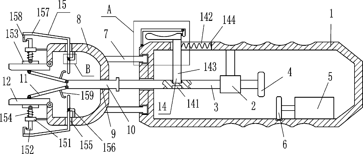
[0019] refer to figure 1 with figure 2 , a hand-held stranding machine for enameled wire, including a cylinder 1, a guide sleeve 2, a round rod 3, a first gear 4, a drive motor 5, a second gear 6, an annular slider 7, a special-shaped frame 8, a square Rod 10, connecting rod 11, splint 12 and drive mechanism 14, guide sleeve 2 is fixedly connected to the top left side of the cylinder body 1, and a circular rod 3 is slidingly installed inside the guide sleeve 2, and the left end of the circular rod 3 runs through the cylinder body 1. In the middle part on the left side, the first gear 4 is fixedly connected to the right end of the circular rod 3. A driving mechanism 14 is provided between the circular rod 3 and the upper left side of the cylinder body 1. The driving motor 5 is installed on the right side of the inner bottom of the cylinder body 1. The output shaft of the drive motor 5 is connected with the second gear 6 through a coupling, and the second gear 6 cooperates wit...

Embodiment 2

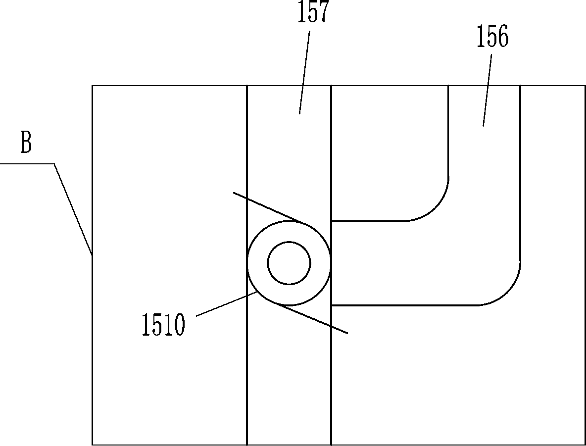
[0024] On the basis of embodiment one, refer to Figure 1-Figure 3, also includes the clamping mechanism 15 that can compress the splint 12, and the clamping mechanism 15 includes a guide sleeve 151, a movable rod 152, a pressing plate 153, a second spring 154, an L-shaped rod 156, an L-shaped contact rod 157, a card Bar 158, fixed bar 159 and torsion spring 1510, guide cover 151 is all installed on the upper and lower sides on the outer left side of special-shaped frame 8, and slide type is provided with movable bar 152 in guide cover 151, and the movable bar 152 inner ends of both sides up and down are all arranged. Hinged with the pressure plate 153 that can compress the splint 12, the second spring 154 is wound between the inside of the movable rod 152 on the upper and lower sides and the inner surface of the guide sleeve 151 on the upper and lower sides. Hole 155, guide hole 155 is provided with L-type contact rod 157, and the left side of L-type contact rod 157 inner sid...

Embodiment 3

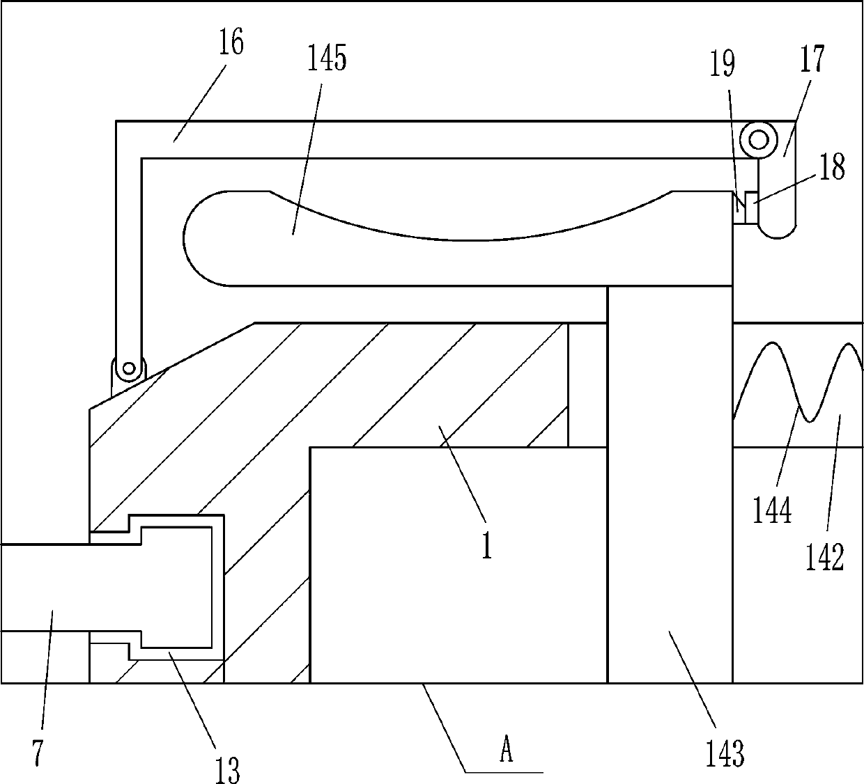
[0027] On the basis of embodiment one and embodiment two, refer to Figure 1-Figure 3 , also includes movable frame 16, movable plate 17, magnet 18 and iron block 19, cylinder body 1 outer top left side is hinged with movable frame 16, movable frame 16 right side is hinged with movable plate 17, movable plate 17 left side The bottom is fixedly connected with a magnet 18 , and the upper part of the right side of the push plate 145 is fixedly connected with an iron block 19 , and the iron block 19 contacts and cooperates with the magnet 18 .

[0028] When the enameled wire moves between the clamping plates 12 on the upper and lower sides, the operator can pull the movable plate 17 to swing upward, and the upward swing of the movable plate 17 drives the magnet 18 to swing upward, and the upward swing of the magnet 18 is separated from the iron block 19, and stops pulling the movable plate 17 , then pull the movable frame 16 to swing upwards without covering the push pedal 145, an...


PUM


Abstract

The invention relates to a stranding machine, and in particular relates to a hand-held stranding machine applied to an enameled wire. The technical problem of the invention is how to design the hand-held stranding machine applied to the enameled wire, which can replace manual twisting of the enameled wire, save labor, can evenly twist the enameled wire, and has high work efficiency. The hand-heldstranding machine applied to the enameled wire comprises a cylinder body, a guide sleeve, a circular rod, a first gear and the like. The guide sleeve is fixedly connected with the top left side of thecylinder body. The circular rod is slidably arranged in the guide sleeve. The left end of the circular rod penetrates the middle of the left side of the cylinder body. The first gear is fixedly connected with the right end of the circular rod. According to the invention, by pushing a push plate to the right, a splint processes and clamps the enameled wire; a drive motor is initiated, and the splint is rotated to drive the enameled wire to be rotated and twisted; the enameled wire becomes a twist knot; manpower does not need to continuously rotate and twist the enameled wire, which is relatively labor-saving; the twisted enameled wire is more uniform; and the work efficiency is high.

Description

technical field [0001] The invention relates to a twisting machine, in particular to a hand-held twisting machine for enameled wires. Background technique [0002] Enameled wire is a main variety of winding wire, which is composed of conductor and insulating layer. After the bare wire is annealed and softened, it is painted and baked many times. However, it is not easy to produce products that meet both standard requirements and customer requirements. It is affected by factors such as raw material quality, process parameters, production equipment, and the environment. Therefore, the quality characteristics of various enameled wires are different, but they all have Mechanical properties, chemical properties, electrical properties, thermal properties four major properties. [0003] After the enameled wire is produced, there are many places that can be used. In the process of processing the network transformer, the enameled wire needs to be used. In order to ensure that the pe...

Claims


Application Information

Patent Timeline
IPC IPC(8): H01B13/02H01B13/06
CPCH01B13/02H01B13/065
Inventor 张艳
Owner 恒达传动禹城有限公司
Why Eureka
Try Eureka