
an ultrasonic probe

An ultrasonic probe and sound head technology, applied in the field of medical equipment, can solve problems such as operator fatigue, affecting operation efficiency, and operator inconvenience, and achieve the effect of ensuring accuracy

Active Publication Date: 2022-06-21
SHENZHEN MINDRAY BIO MEDICAL ELECTRONICS CO LTD +1
View PDF0 Cites 0 Cited by
  • Summary
  • Abstract
  • Description
  • Claims
  • Application Information

AI Technical Summary

Problems solved by technology

However, this operation requires the operator’s wrist to be rotated accordingly, which will bring inconvenience to the operator, especially when repeated measurements are performed many times, it is easy to cause operator fatigue and affect operating efficiency

Method used


Image

  • an ultrasonic probe
  • an ultrasonic probe
  • an ultrasonic probe

Examples


Embodiment Construction

[0036] The present invention will be further described in detail below through specific embodiments in conjunction with the accompanying drawings. Wherein, similar elements in different implementations adopt associated similar element numbers. In the following implementation manners, many details are described for better understanding of the present application. However, those skilled in the art can readily recognize that some of the features can be omitted in different situations, or can be replaced by other elements, materials, and methods. In some cases, some operations related to the application are not shown or described in the description, this is to avoid the core part of the application being overwhelmed by too many descriptions, and for those skilled in the art, it is necessary to describe these operations in detail Relevant operations are not necessary, and they can fully understand the relevant operations according to the description in the specification and genera...


PUM


Abstract

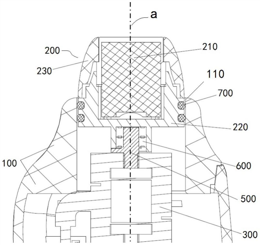
An ultrasonic probe, the sound head (210) is rotatably installed in the casing (100), and the rotation axis of the sound head (210) is set along the front and rear directions of the probe, so that the sound head (210) can Its axis of rotation turns. When the operator uses the probe, the front end of the sound head (210) will be attached to the subject with a certain pre-pressure, and the sound head (210) will automatically rotate and slide to the intercostal area (the area between the ribs) under the action of the pre-pressure , so that the sound head (210) avoids the influence of ribs. At this time, the operator can still use the usual grip to hold the probe, but since the sound head (210) can rotate, at this time the sound head (210) can be rotated between the ribs to form a state parallel to the ribs, thus ensuring The accuracy of the detection does not require the operator to rotate the wrist to adapt to the rotation of the sound head (210).

Description

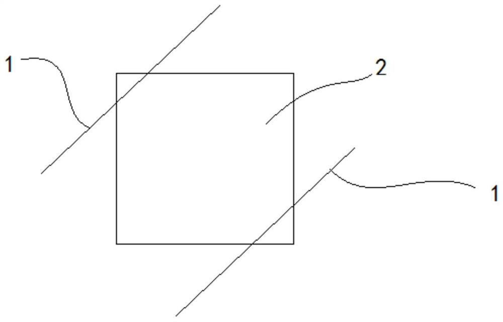
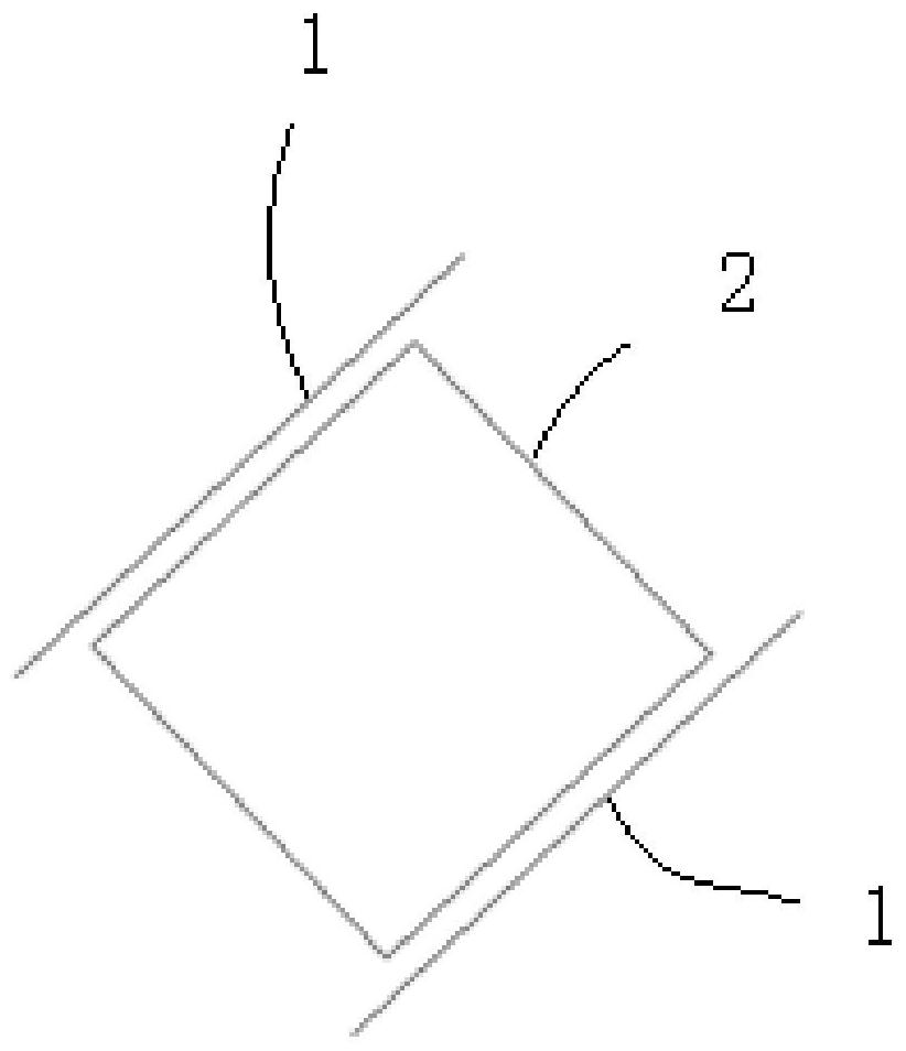
technical field [0001] The present application relates to a medical device, in particular to a probe structure of an ultrasonic device. Background technique [0002] An ultrasonic probe is a necessary part of an ultrasonic device, which usually has a sound head for emitting and receiving ultrasonic waves and a trigger button for controlling the working state of the probe. During detection, the operator holds the probe and contacts the front end of the acoustic head with the subject to be tested. The acoustic head emits ultrasonic waves and receives reflected ultrasonic waves to form an image for the operator's reference. [0003] Usually, the operator is used to pressing the trigger button with the thumb. When the subject is lying flat, the ribs of the subject are at a certain angle to the ground. At this time, the operator uses the probe to scan according to the usual holding posture. Since the trigger button of the probe and the sound head have a fixed relative position r...

Claims


Application Information

Patent Timeline
Patent Type & Authority Patents(China)
IPC IPC(8): A61B8/00A61B8/08
CPCA61B8/4444A61B8/0875A61B8/00A61B8/08
Inventor 郑洲李双双唐明吴飞
Owner SHENZHEN MINDRAY BIO MEDICAL ELECTRONICS CO LTD
Learn More