Low-water-mist flushing device

A technology of flushing water and water mist, which is applied in the direction of electrical components, semiconductor/solid-state device manufacturing, circuits, etc. It can solve the problems of target observation obstruction, machine service life impact, and poor effect, etc., to solve the problem of water mist Effect

Inactive Publication Date: 2019-12-17
SEMTEK CORP
View PDF6 Cites 1 Cited by
  • Summary
  • Abstract
  • Description
  • Claims
  • Application Information

AI Technical Summary

Problems solved by technology

[0002] In today's semiconductor wet process, there are many cleaning procedures. Through the process of flushing, the application of different targets is carried out. While flushing, it is inevitable that a large amount of water mist will be generated, which has certain effects on the target observation. Obstacles, but also have a certain

Method used


Image

  • Low-water-mist flushing device
  • Low-water-mist flushing device
  • Low-water-mist flushing device

Examples


Embodiment Construction

[0040] The following is a detailed description based on the embodiment shown in the drawings:

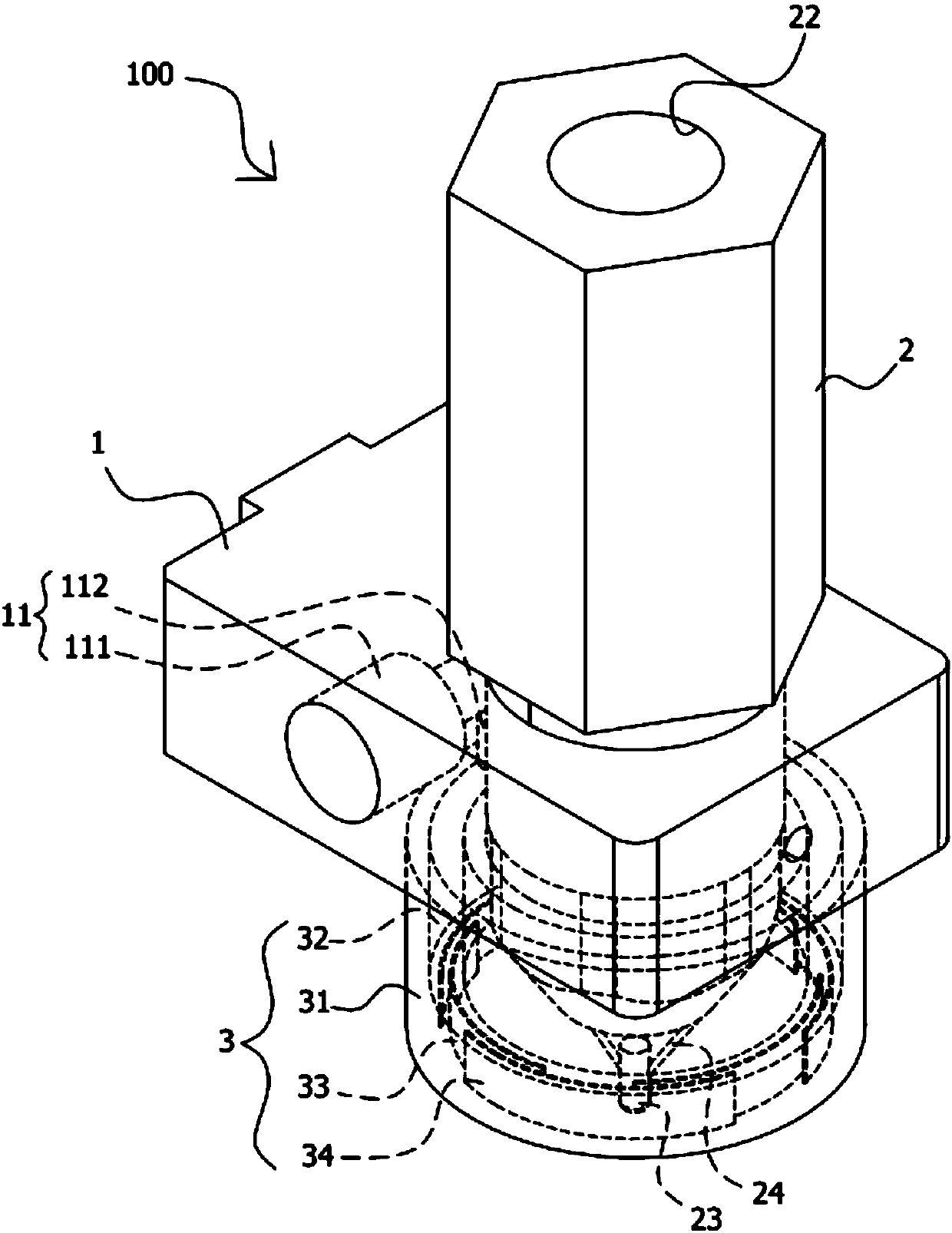
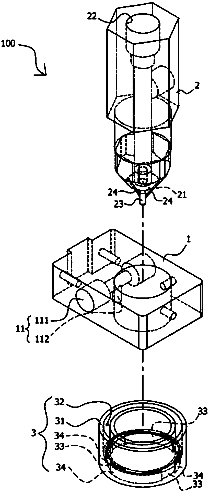
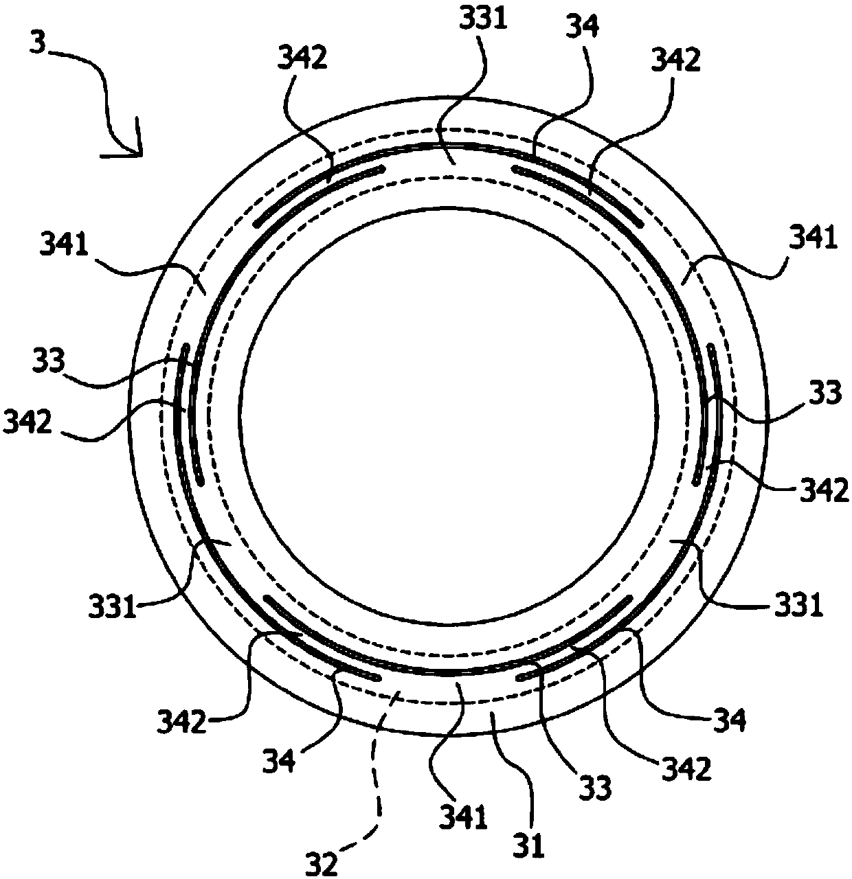
[0041] Such as Figure 1 to Figure 5 As shown in the figure, it is disclosed that a low water mist flushing device can be used in conjunction with wet process equipment, wherein the low water mist flushing device 100 includes a positioning unit 1, a flushing unit 2, and a The air knife cap 3; the positioning unit 1, one end of which can be connected to the corresponding side of the wet process equipment, and has an air guide channel 11 capable of outputting gas to the bottom side; the flushing unit 2, which is vertically arranged on the positioning At the free end of the unit 1, there is a water outlet 21 at the bottom and a water inlet 22 at the top; the air knife cap 3 includes an annular housing 31, a slot 32, at least two internal air outlets slit 33, and at least two air outlet slits 34; the annular shell 31, which is sleeved outside the water outlet 21; the slot 32, which is ...


PUM


Abstract

The invention provides a low-water-mist flushing device. The low-water-mist flushing device can prevent a process from being affected by the generation of water mist. According to the technical means,the low-water-mist flushing device includes a positioning unit, a flushing unit and an air knife cap; one end of the positioning unit can be connected with the corresponding side of wet process equipment and an air guiding channel is arranged at one end of the positioning unit; the flushing unit is vertically arranged at the free end of the positioning unit and is provided with a water outlet anda water inlet; the air knife cap comprises an annular shell, a slot, inner air outlet seams and outer air outlet seams, wherein the inner air outlet seams and the outer air outlet seams communicate with the slot; the annular shell is arranged outside the water outlet in a sleeving manner; the slot is formed in the top end of the vertical wall surface of the annular shell and can correspond to theair guiding channel; the inner air outlet seams are arranged on the inner side of the bottom end of the vertical wall surface of the annular shell, and first gaps are formed between the inner air outlet seams; and the outer air outlet seams are arranged on the outer side of the bottom end of the vertical wall surface of the annular shell in an annular mode, second gaps are formed between the outer air outlet seams, gaps are formed between the outer air outlet seams and the inner air outlet seams, and the outer air outlet seams further correspond to one first gap.

Description

technical field [0001] The invention relates to a flushing structure on wet process equipment, in particular to a low water mist flushing device. Background technique [0002] In today's semiconductor wet process, there are many cleaning procedures. Through the process of flushing, the application of different targets is carried out. While flushing, it is inevitable that a large amount of water mist will be generated, which has certain effects on the target observation. Obstacles, but also have a certain degree of impact on the service life of the machine. [0003] In response to the problem of water mist, the wet process equipment will also be equipped with an air extraction device. While flushing, the air extraction device will be used to extract the water mist to reduce the impact of the water mist, but overall, the effect is not very good. . [0004] In view of this, how to provide a low water mist flushing device that can solve the aforementioned problems and avoid th...

Claims


Application Information

Patent Timeline
IPC IPC(8): B08B3/02B08B13/00H01L21/67
CPCB08B3/02B08B13/00H01L21/67023H01L21/67028
Inventor 蔡韶庭王森泰
Owner SEMTEK CORP
Why Eureka
Try Eureka