
Pipe bending machine for machining pipes for automobile production and manufacturing and using method of pipe bending machine

A technology for pipe bending machines and pipe fittings, which is applied to manufacturing tools, metal processing equipment, feeding devices, etc., can solve problems such as reducing the working efficiency of pipe bending machines and increasing people's labor pressure, saving time, reducing labor pressure, and improving convenient effect

Active Publication Date: 2019-12-17
湖南容光汽车部件有限公司
View PDF5 Cites 10 Cited by
  • Summary
  • Abstract
  • Description
  • Claims
  • Application Information

AI Technical Summary

Problems solved by technology

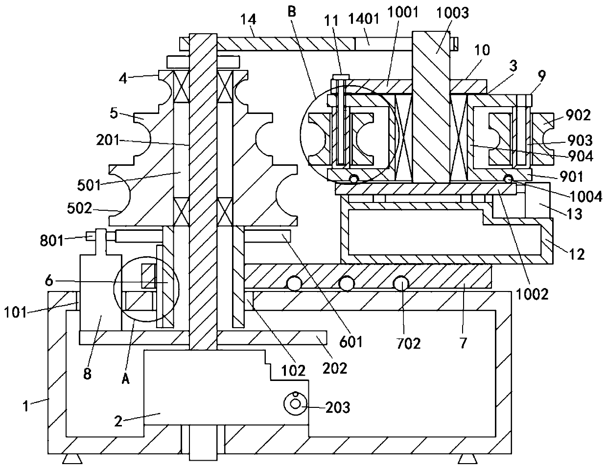
[0003] However, when the existing pipe bending machine needs to process pipe fittings of different diameters, it is often necessary to manually replace the wheel molds and clamping dies of different sizes according to the size of the pipe fittings, which will increase people's labor pressure and reduce the work of the pipe bending machine. Efficiency; therefore, it is necessary to study a pipe bending machine for pipe fittings processing in automobile manufacturing to improve the replacement efficiency of the wheel die and clamping die of the pipe bender

Method used


Image

  • Pipe bending machine for machining pipes for automobile production and manufacturing and using method of pipe bending machine
  • Pipe bending machine for machining pipes for automobile production and manufacturing and using method of pipe bending machine
  • Pipe bending machine for machining pipes for automobile production and manufacturing and using method of pipe bending machine

Examples


Embodiment Construction

[0043] The following will clearly and completely describe the technical solutions in the embodiments of the present invention with reference to the accompanying drawings in the embodiments of the present invention. Obviously, the described embodiments are only some, not all, embodiments of the present invention. Based on the embodiments of the present invention, all other embodiments obtained by persons of ordinary skill in the art without creative efforts fall within the protection scope of the present invention.

[0044] In the description of the present invention, it should be understood that the terms "disposition", "open", "bottom", "top", "axial", "inner", "circumferential side", etc. indicate orientation or positional relationship, and only It is for the convenience of describing the present invention and simplifying the description, but does not indicate or imply that the components or elements referred to must have a specific orientation, be constructed and operated in...


PUM


Abstract

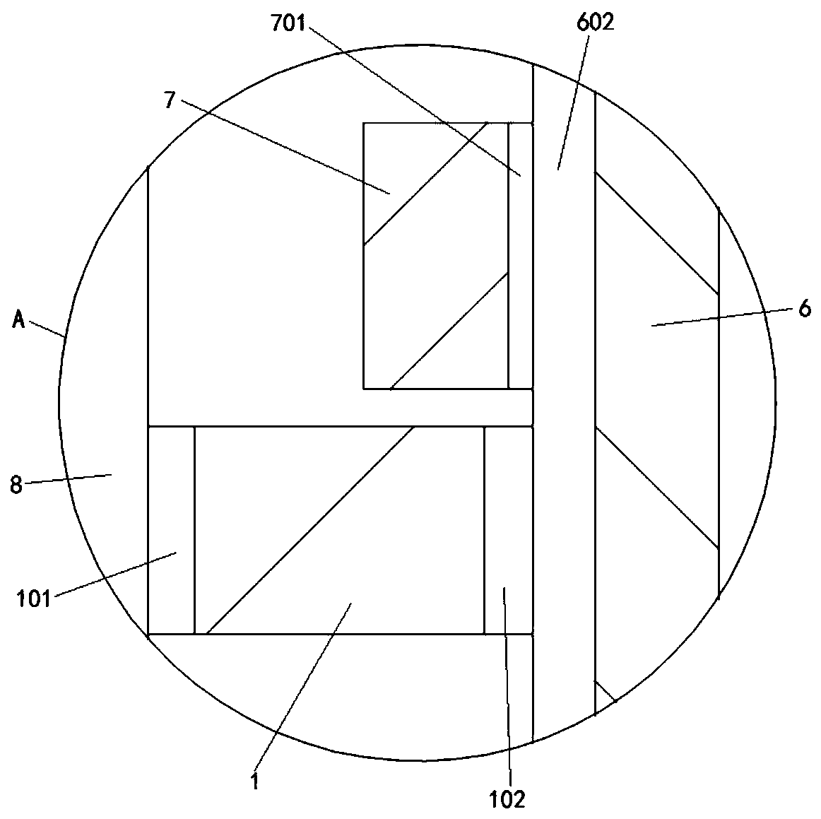
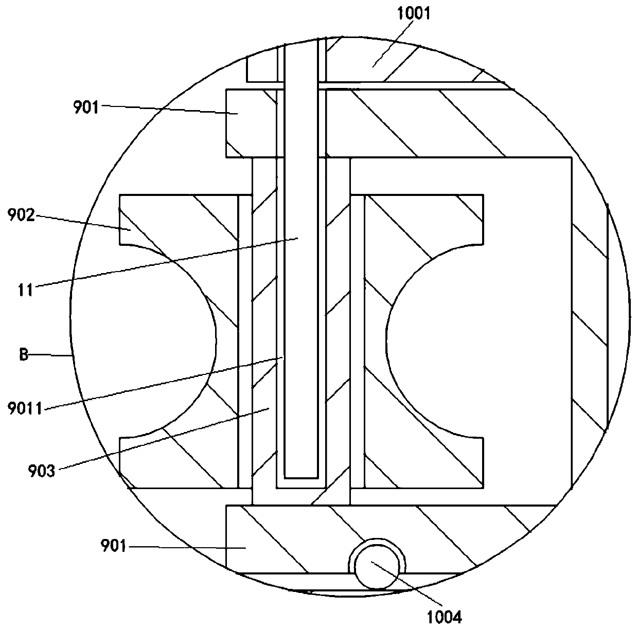
The invention discloses a pipe bending machine for machining pipes for automobile production and manufacturing and a using method of the pipe bending machine, and relates to the technical field of pipe bending machines. The pipe bending machine comprises a shell, a spiral elevator and a rotary disc; the spiral elevator is mounted in the shell, and the spiral elevator comprises a screw rod; a motorport and a lifting port are correspondingly formed in the upper surface of the shell; the top end of the screw rod penetrates through the lifting port and is rotationally connected with a stepped wheel die; and a supporting plate is fixed to the bottom end of the screw rod. According to the pipe bending machine, the stepped wheel die is driven to ascend and descend through the spiral elevator, afixing frame is used as a base to rotate a rotating die manually, and finally under the driving of a hydraulic cylinder, the pipe is clamped by a clamping die and an annular groove matched with the pipe; and final a motor drives the stepped wheel die and the rotary disc through meshing transmission of a second gear and a first gear to rotate by taking the screw rod as a rotating center, bending treatment of the pipe is achieved, the replacement efficiency of the stepped wheel die and the clamping die can be improved, the labor pressure of people is relieved, and the production efficiency of the pipe bending machine is improved.

Description

technical field [0001] The invention belongs to the technical field of pipe benders, and in particular relates to a pipe bender for processing pipe fittings for automobile production and a method for using the same. Background technique [0002] In daily life, pipe fittings with different degrees of twist or curvature are often required to meet the actual use and performance requirements of the equipment, so people often use pipe benders to bend pipe fittings of different diameters; and pipe benders are roughly divided into CNC Pipe benders, hydraulic pipe benders, etc.; and the processing of parts such as oil pipes and exhaust pipes on automobiles also requires pipe benders. Because of their simple operation and high work efficiency, pipe benders play an important role in the manufacturing industry. status. [0003] However, when the existing pipe bending machine needs to process pipe fittings of different diameters, it is often necessary to manually replace the wheel mold...

Claims


Application Information

Patent Timeline
IPC IPC(8): B21D7/024B21D43/00
CPCB21D7/024B21D43/003
Inventor 吴磊朱明祥杨刚
Owner 湖南容光汽车部件有限公司
Learn More