Synchronous clamping eccentricity detection device for circular workpiece

An eccentricity detection, circular workpiece technology, applied in measuring devices, mechanical measuring devices, mechanical devices, etc., can solve the problem of not being able to find the axis offset when the cylindrical workpiece to be welded is clamped in time, so as to improve the welding performance. The effect of quality and stability

Pending Publication Date: 2019-12-17
CHONGQING UNIVERSITY OF SCIENCE AND TECHNOLOGY
View PDF0 Cites 6 Cited by
  • Summary
  • Abstract
  • Description
  • Claims
  • Application Information

AI Technical Summary

Problems solved by technology

[0008] In order to solve the problem that the axial center deviation cannot be found in time when the cylindrical workpiece to be welded is clamped, the present invention provides a

Method used


Image

  • Synchronous clamping eccentricity detection device for circular workpiece
  • Synchronous clamping eccentricity detection device for circular workpiece
  • Synchronous clamping eccentricity detection device for circular workpiece

Examples


Embodiment 1

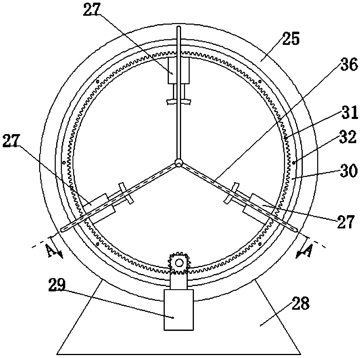
[0049] Such as Figure 1 to Figure 2 As shown, a circular workpiece synchronous clamping eccentricity detection device includes a detection device body and a clamping rotation mechanism, and the detection device body is arranged on the clamping rotation mechanism;

[0050] The clamping and rotating mechanism includes an annular mounting base 25, an installation inner cylinder 31, and an installation base 28. The outer wall of the annular mounting base 25 is fixed on the mounting base 28, and the centerline of the annular mounting base 25 is horizontal. set up;

[0051] The annular mounting seat 25 is cylindrical, the centerline of the annular mounting seat 25 is arranged horizontally, the inner cavity of the annular mounting seat 25 forms the clamping area, and the detection device body surrounds the annular mounting seat 25 centerline; the annular mounting seat 25 and the installation inner cylinder 31 are concentrically arranged, and the installation inner cylinder 31 is in...

Embodiment 2

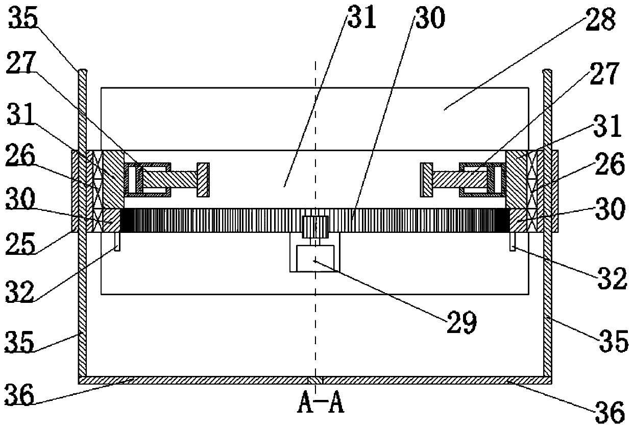
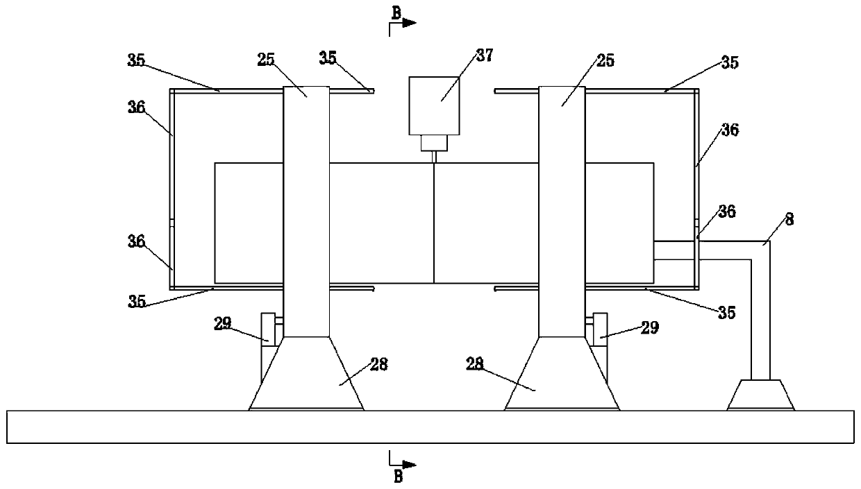
[0061] Such as Figures 3 to 18 As shown, a cylindrical workpiece friction stir welding system includes a workbench, which is provided with an inner support device, a welding tool (not shown in the figure) and two sets of clamping and rotating mechanisms. The inner support device Located between the two sets of clamping and rotating mechanisms, the stirring head 37 of the welding tool is located above the inner support device;

[0062] The clamping and rotating mechanism includes an annular mounting base 25, an installation inner cylinder 31, and an installation base 28. The outer wall of the annular mounting base 25 is fixed on the mounting base 28, and the centerline of the annular mounting base 25 is horizontal. Set, the installation base 28 is slidably fitted on the workbench, the centerlines of the ring mounting seats 25 of the two groups of clamping and rotating mechanisms coincide, and the sliding direction of the mounting base 28 is the same as that of the ring mountin...


PUM


Abstract

The invention discloses a synchronous clamping eccentricity detection device for a circular workpiece. The synchronous clamping eccentricity detection device comprises a detection device body and a clamping-rotating mechanism, the detection device body is arranged on the clamping-rotating mechanism, the clamping-rotating mechanism comprises a cylindrical annular mounting base, a clamping area is formed in an inner cavity of the annular mounting base, and the detection device body is arranged around the center line of the annular mounting base; and the detection device body comprises a slidingpart and a detection part, the sliding part is movably inserted into the cylinder wall of the annular installation base in a penetrating mode, the detection part is fixedly installed on the sliding part, and an alignment mark is arranged on the detection part. According to the synchronous clamping eccentricity detection device for the circular workpiece, after that the cylindrical workpiece to bewelded is fixed, whether the cylindrical workpiece is offset can be determined, a clamping cylinder is adjusted in time, the rotating stability of the cylindrical workpiece during welding is ensured,and the welding quality is improved.

Description

technical field [0001] The invention relates to a detection device, in particular to a circular workpiece synchronous clamping eccentricity detection device. Background technique [0002] Friction stir welding refers to the use of the heat generated by the friction between the high-speed rotating welding tool and the workpiece to locally melt the welded material. When the welding tool moves forward along the welding interface, the plasticized material is under the action of the rotating friction of the welding tool. It flows from the front of the welding tool to the rear, and forms a dense solid-phase weld under the extrusion of the welding tool. When using friction stir welding to weld two cylindrical workpieces to be welded, the ends of the two cylindrical workpieces to be welded should be pressed tightly, and the two cylindrical workpieces to be welded are fixed by a clamping device, and the welding tool Fixed, the welding stirring head extends into the seam from the out...

Claims


Application Information

Patent Timeline
IPC IPC(8): G01B5/252B23K20/26B23K20/12
CPCB23K20/122B23K20/26G01B5/252
Inventor 王刚零的应姚宗湘陈玉华苏子龙
Owner CHONGQING UNIVERSITY OF SCIENCE AND TECHNOLOGY
Why Eureka
Try Eureka