
Positioning error compensation method and system based on RFID positioning technology

A technology of positioning error and positioning technology, which is applied in the direction of measuring devices, instruments, induction recording carriers, etc., can solve the problems of inability to large-scale application and expensive implementation, and achieve the effect of solving the problem of inability to locate and eliminating accumulated positioning errors.

Pending Publication Date: 2019-12-17
SHANGHAI ORIENTAL MARITIME ENG TECH CO LTD
View PDF2 Cites 10 Cited by
  • Summary
  • Abstract
  • Description
  • Claims
  • Application Information

AI Technical Summary

Problems solved by technology

After research, the applicant found that the invention relies on sensing the RFID electronic tag to trigger image capture to calculate the precise position during the vehicle's travel. To achieve such an effect, the content of the captured image needs to include the vehicle and the milepost along the railway line. Correspondingly, It is required that the shooting device has the ability to shoot at night, and can adapt to the time delay at different speeds, and the cost of implementation is too expensive to be applied on a large scale

Method used


Image

  • Positioning error compensation method and system based on RFID positioning technology
  • Positioning error compensation method and system based on RFID positioning technology
  • Positioning error compensation method and system based on RFID positioning technology

Examples


Embodiment 1

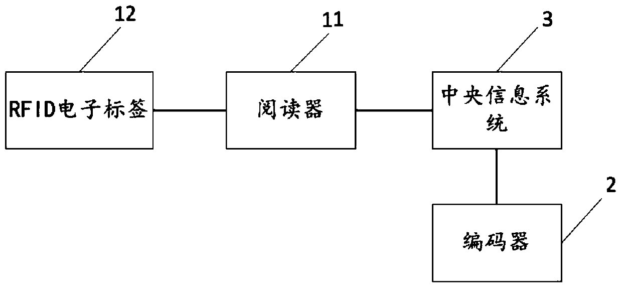
[0036] Such as figure 1 As shown, a positioning error compensation system based on RFID positioning technology includes an RFID positioning system 1. The RFID positioning system 1 includes one or two readers 11, several RFID electronic tags 12, a central information system 3, and an encoder 2. , Encoder 2 is set on a double-track steel rail flaw detection vehicle, and is used to count the number of wheel rotations and speeds calculated by the encoder to reflect the mileage and speed of the vehicle. Here, how does the encoder 2 count the number of wheel rotations and The speed can be referred to the prior art, and will not be repeated here; the central information system 3 obtains the number of wheel rotations and speeds calculated by the encoder, and calculates the current mileage according to the encoder coefficient and the number of wheel rotations, and records it as the first mileage, where , The initial value of the encoder coefficient is a preset value stored in the centra...

Embodiment 2

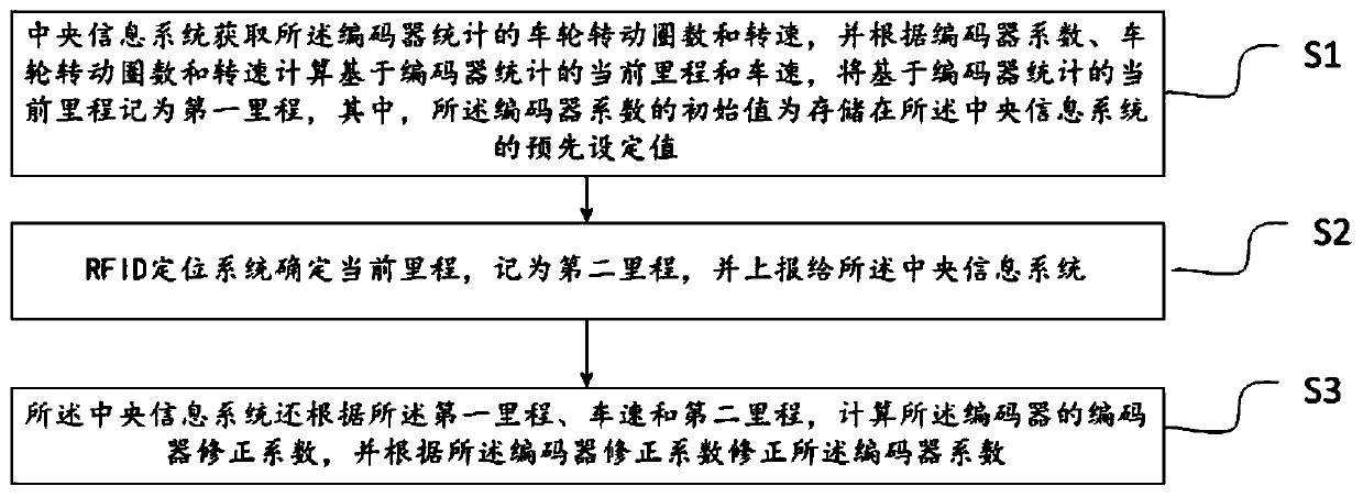
[0050] Based on the error compensation system of Embodiment 1, the embodiment of the present invention also provides a positioning error compensation method based on RFID positioning technology, which corrects the encoder's mileage positioning information based on the mileage information determined by the RFID positioning system positioning to obtain more accurate Mileage positioning information. Such as figure 2 As shown, including the following steps:

[0051] S1: The central information system obtains the number of wheel rotations and speeds counted by the encoder, and calculates the current mileage and vehicle speed based on the encoder statistics based on the encoder coefficient, the number of wheel rotations and the speed, and will record the current mileage based on the encoder statistics Is the first mileage, wherein the initial value of the encoder coefficient is a preset value stored in the central information system;

[0052] The encoder counts the number of wheel rota...


PUM


Abstract

The invention discloses a positioning error compensation method and system based on an RFID positioning technology. The method comprises the steps that a central information system acquires the numberof turns and the rotating speed of wheels counted by an encoder, the present mileage and vehicle speed counted on the basis of the encoder are calculated according to an encoder coefficient whose initial value is a preset value stored in the central information system, the number of turns of the wheels and the rotating speed of the wheels, and the present mileage counted on the basis of the encoder is recorded as first mileage; an RFID positioning system determines the present mileage, records the present mileage as second mileage and reports the second mileage to the central information system; and the central information system calculates an encoder correction coefficient according to the second mileage, the vehicle speed and the first mileage, and the encoder coefficient is corrected according to the encoder correction coefficient. Thus, the positioning error compensation method and system based on the RFID positioning technology can corrected mileage counted by the encoder and realizes accurate positioning.

Description

Technical field [0001] This application relates to the technical field of flaw detection and positioning, and in particular to a positioning error compensation method and system based on RFID positioning technology. Background technique [0002] At present, the medium-sized dual-track flaw detection vehicles used in China, whether it is flaw detection system, rail monitoring system, track bed inspection system, tunnel inspection system, etc., basically use vehicle-mounted encoders for auxiliary positioning; positioning with encoders requires user input to start Mileage, and need to calculate the mileage based on the parameters provided by the encoder, and then get the end mileage. Because the mileage calculation is affected by the wheel diameter, track wear, track curve and other factors, the distance between the mileage calculated by the encoder and the actual mileage There are errors. Therefore, the method of auxiliary positioning using a vehicle-mounted encoder is prone to cum...

Claims


Application Information

Patent Timeline
Patent Type & Authority Applications(China)
IPC IPC(8): G01C21/16G01C25/00G06K7/00
CPCG01C21/165G01C25/00G06K7/0008
Inventor 余天乐毛少虎陆旭红姚继东盛忠义吴宴华廉凯
Owner SHANGHAI ORIENTAL MARITIME ENG TECH CO LTD
Learn More