Split-type switch patch board

A plug-in, split-type technology, which is applied to devices with bendable leads, electrical components, bases/shells, etc., can solve problems such as poor applicability, inability to adjust the length of the power cord, and inconvenient opening and closing of the plug-in panel. To improve the applicability, the room is neat and beautiful, and the use is convenient.

Pending Publication Date: 2019-12-17
WUHAN INSTITUTE OF TECHNOLOGY
View PDF0 Cites 0 Cited by
  • Summary
  • Abstract
  • Description
  • Claims
  • Application Information

AI Technical Summary

Problems solved by technology

At present, the power strip is generally placed in the corner, but this also brings inconvenience to us to open and close the power strip; in addition, the length of the power cord cannot be adjusted, and the applicability is poor

Method used


Image

  • Split-type switch patch board
  • Split-type switch patch board
  • Split-type switch patch board

Examples


Embodiment 1

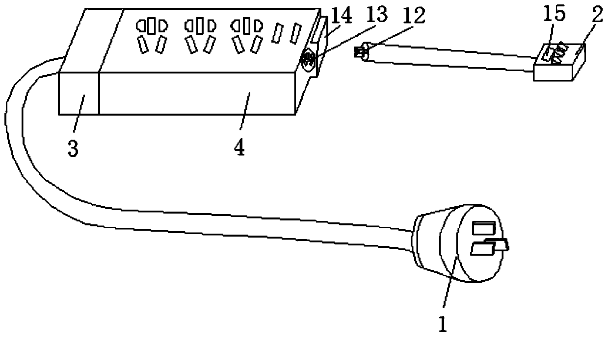
[0037] On the basis of the above structure, in this embodiment, the box body switch 2 is fixedly installed with an indicator light 15 showing its working status, which is convenient for people to know the usage status of the socket. In addition, a plurality of switch buttons are installed on the box body switch 2, and the plurality of switch buttons are respectively used to control different socket power sources.

Embodiment 2

[0039] On the basis of Embodiment 1, in this embodiment, the winding device includes a winding shaft 5, and the two ends of the winding shaft 5 are positioned to be rotatably connected to two opposite sides of the wire storage box 3, and on two opposite sides of the wire storage box 3 There are rotating holes matched with both ends of the winding shaft 5; the second power cord is wound on the winding shaft 5, and the winding shaft 5 is rotated to wind or release the second power cord to adjust the length of the second power cord. The structure is simple, and the length of the second power cord can be adjusted by means that those skilled in the art can think of, such as manually turning the bobbin 5 forward or reverse so that the second power cord is wound on the bobbin or released from the bobbin.

[0040] It should be noted that the bobbin 5 can be installed in the wire storage box 3 to rotate vertically, and can also be installed in the wire storage box 3 to rotate horizontal...

Embodiment 3

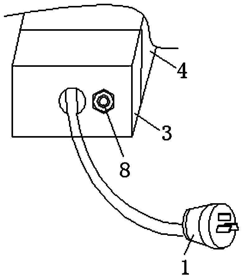
[0042] On the basis of Embodiment 2, in this embodiment, one end of the winding shaft 5 is coaxially fixed with a positioning disc 6, and the center of the positioning disc 6 is provided with a through hole for the winding shaft 5 to pass through, and the positioning disc 6 passes through this The way those skilled in the art can think of is fixed on the winding shaft 5, such as welding, which is convenient for disassembly and assembly. A plurality of positioning holes 7 are evenly spaced on the circumferential surface of the positioning plate 6; The hole internal thread is connected with set screw 8. In the process of adjusting the second power line, tighten or loosen the positioning screw 8 until one end of it is inserted into or withdrawn from one of the positioning holes 7 to fix or loosen the positioning plate 6. The structure is simple, the operation is simple, the positioning is convenient and quick, and the Save time and effort.

[0043] It should be noted that the po...


PUM


Abstract

The invention relates to a split switch patch board which comprises a plug, a socket and a box switch. The socket is composed of a wire storage box and a socket box. One end of the socket box is connected with the box switch through a first power line, and the other end of the socket box is fixedly connected with one end of the wire storage box. A wire winding device is rotatably installed and positioned in the wire storage box. The two ends of the wire storage box are provided with openings. The plug is connected with one end of a second power line. The other end of the second power line penetrates through the opening on the other end of the wire storage box and is wound on the wire winding device and then penetrates through the opening on one end of the wire storage box and is connectedwith the other end of the socket box. The split switch patch board has the beneficial effects that the split switch is adopted, the patch board is convenient to open and close and the use is convenient; in addition, the length of the patch board power line can be adjusted according to requirements and thus the applicability is high and use is convenient.

Description

technical field [0001] The invention relates to the technical field of plug-in boards, in particular to a split-type switch plug-in board. Background technique [0002] In home life, office work and travel, you need to use the power strip, which has played the function of safely connecting electrical appliances, and is a safe and convenient power conversion appliance. The power can be turned on quickly and conveniently through the switch on the plug board, and it is safe to use. At present, the power strip is generally placed in the corner, but this also brings inconvenience to us to open and close the power strip; in addition, the length of the power cord cannot be adjusted, and the applicability is poor. Contents of the invention [0003] The technical problem to be solved by the present invention is to provide a split-type switch plug-in board, which adopts a split-type switch, which is convenient for opening and closing the plug-in board, and is easy to use; in additi...

Claims


Application Information

Patent Timeline
IPC IPC(8): H01R13/70H01R13/72H01R13/717H01R13/502H01R13/52H01F27/00
CPCH01F27/00H01R13/502H01R13/5213H01R13/70H01R13/717H01R13/72
Inventor 李芳高杰陈绪兵
Owner WUHAN INSTITUTE OF TECHNOLOGY
Why Eureka
Try Eureka